")
")

Since its inception in 2004, SMC Testing Pty Ltd has conducted over 50,000 SMC Tests on behalf of the majority of the world's mining companies. These tests cover nearly 2000 different ore bodies across 100 countries and constitute one of the largest data bases of its kind in the world. The SMC Test, unlike any other comminution test available on the market, enables both power-based calculations and simulation studies to be conducted. It has been proven through benchmarking against an unprecedented 120 processing plants around the world, covering just about every type of comminution circuit in operation, including the largest to the smallest equipment available on the market, and treating from some of the softest to the hardest ores that have been discovered to date. This enables the SMC Test® to provide unparalleled versatility, precision and accuracy compared to other alternatives.
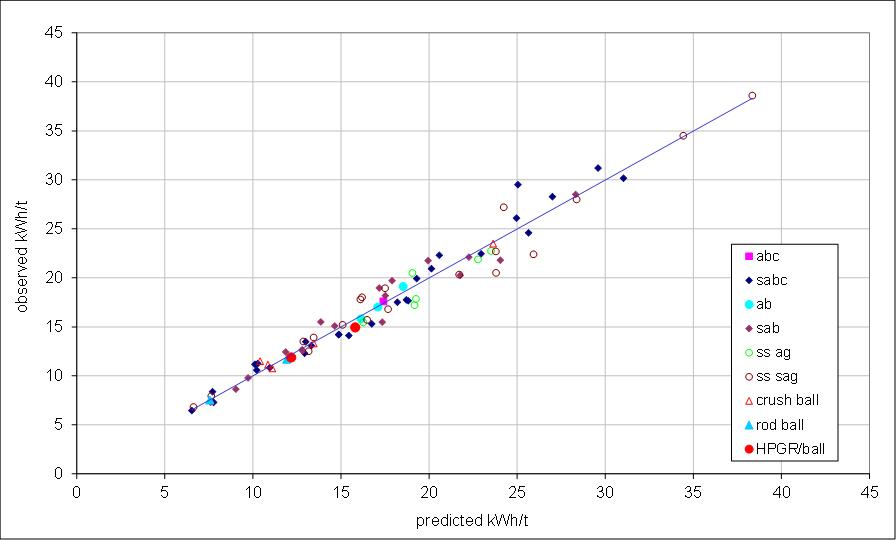
Predicted Comminution Circuit Specific Energy Using The SMC Test Compared to Values Measured from Over 120 Operating Plants from Around the World
ABOUT THE SMC TEST
The SMC Test is a laboratory comminution test which provides a range of information on the breakage characteristics of rock samples for use in the mining/minerals processing industry.
The SMC Test was developed by Dr Steve Morrell as a cost-effective means of providing accurate data on the breakage characteristics of rock samples which can be used for a range of purposes including comminution circuit design and optimization, ore body profiling, geometallurgical modelling and Mine-to-Mill studies. The test was originally developed to allow the use of small quantities (a few kilograms) of quartered (slivered) small diameter drill core, although whole core, half core and lump rock can also be used with ease.
The SMC Test is available commercially through a world-wide network of over 30 independent labs in Europe, Australia, North America, South America, China, Russia, Asia and Africa. In-house licenses are also held by a number of major mining companies such as Anglo American, Barrick, Newmont Mining, Teck and Freeport-McMoRan.
For information on the cost to conduct SMC Tests please contact your nearest licensed metallurgical laboratory.
TESTED ORE TYPES / COMMODITIES
- Aluminium-Bauxite
- Aluminium-Cryolite
- Cement Clinker
- Chrome
- Coal-Metallurgical
- Coal-Rejects
- Cobalt
- Copper-Ore
- Copper-Slag
- Diamond
- Ferrochrome
- Fluorspar
- Gold
- Graphite
- Ilmenite
- Indium
- Iodine
- Iron-Hematite
- Iron-Magnetite
- Iron-Pellets
- K-Feldspar
- Lead-Ore
- Lead-Slag
- Limestone
- Lithium
- Magnesite
- Manganese
- Mineral Sands
- Molybdenum
- Nickel
- Niobium
- Oil Shale
- Palladium
- Platinum
- Phosphate
- Polymetalic sulphides
- Potash
- Quarry rock
- Quartzite
- Rare Earths
- Silver
- Tantalum
- Tin
- Titanium
- Tungsten
- Uranium
- Vanadium
- Zinc