



The content on this page was automatically generated from the PDF publication document and may contain errors or inaccuracies. Please refer to the original PDF for the most accurate information.
A LABORATORY STUDY OF THE PERFORMANCE CHARACTERISTICS OF MILL PULP LIFTERS
S.R. LATCHIREDDI and S.MORRELL
JKMRC,
Isles
Rd.,
Indooroopilly, Qld. 4068, Australia. E-mail:
ABSTRACT
Although pulp lifters are an integral part of the majority of grate discharge grinding mills, the potential problems imposed due to their improper design have only come to light in recent years. Ideally, at a particular mill hold-up, the discharge rate through a grate-only assembly should be matched by the capacity of the pulp lifters. Recent industrial experience has suggested that this is not always the case and can lead to a dramatic reduction in mill capacity. A research program was therefore initiated at the JKMRC to study this aspect of mill operation.
This paper presents the results obtained to date from experiments carried out in a laboratory SAG mill with grate-only as well as grate and pulp lifter arrangements. Scale models of industrial pulp lifter designs were used. The results illustrate the influence of pulp lifter chamber volume and show that over a wide range of values, the discharge capacity of the pulp lifter assembly was always less than that of a grate-only configuration. The cause of this problem is explained together with comparisions of different pulp lifter designs. © 1997 Elsevier Science Ltd
Keywords
SAG milling; grinding; comminution
INTRODUCTION
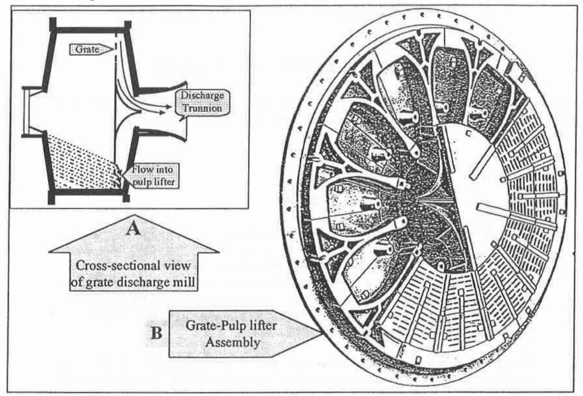
Pulp lifters (also known as pan lifters) are an important component of grate discharge mills. Their purpose is to transport slurry passing through the grate out of the mill via the discharge trunnion. In conjunction with the grate open area, the performance of the pulp lifters dictate the volumetric discharge rate of slurry out of the mill. The cross-section of a typical low level grate discharge mill (A) with pulp lifters positioned between the grate and the discharge trunnion as well as their general arrangement (B) is shown in Figure 1.
There are two main types of pulp lifter currently in use
- radial, and
- spiral.
Though it has been claimed that spiral lifters are more efficient [1], the radial type are the most commonly used in the mineral processing industry. As the mill rotates each grate/pulp lifter segment passes through the slurry pool where the slurry flows through the grate and accumulates in the pulp lifter chamber. With further rotation of the mill the pulp lifter and its slurry contents are raised and the slurry begins to flow down the radial face of the pulp lifter towards the centre of the mill. The slurry is deflected at this point so it flows through the trunnion and out of the mill.
Although pulp lifters are obviously important in determining the ultimate discharge flow capacity, very little research has been conducted/reported either on their performance or on their effect on mill efficiency. One of the main exceptions is the work of Mokken and co-workers [2] which provided no quantitative results, but claimed the following based on their experience:
- only one third of the holes in the grate are effectively utilised in pulp lifter discharge mills compared to end discharge mills.
- the flow-back or short-circuiting of slurry from pulp lifters into the mill increases with mill speed and hinders optimisation of the mill speed.
- the pulp gradient inside the mill is reduced when pulp lifters are used due to higher pulp levels.
Rowland and Kjos [3] also stated that the load carrying capacity of pulp lifters is more important than grate slot area for a successful mill operation. They also claimed that if the pulp lifters do not have enough capacity, the typical approach of increasing grate area does not improve the situation but makes it worse by allowing the slurry to flow back into the mill. This causes it to run too wet which reduces the grinding efficiency. Despite these observations, a decade later both Bond [4] and Kjos [5] reiterated the importance of pulp lifter assembly design and stated that the problems associated with them had yet to be solved. However, comparing the discharge mechanism in both radial and spiral pulp lifters, Burgess [1] mentioned that the latter allowed slurry to discharge more quickly and so avoided the risk of carryover. He also claimed an increase in grinding efficiency with spiral pulp lifters.
Unfortunately, there are no published data either to substantiate these claims or to understand what relationship exists between the performance of pulp lifters and mill operation.
Given this lack of published data, a research programme was initiated in this area at the JKMRC in 1992 to study grate flow [6]. This was extended to look at flow through a simple pulp lifter arrangement [7]. This study has been further extended to look more closely at the effect of pulp lifter design, the results from which are reported in this paper.
METHODS AND MATERIALS
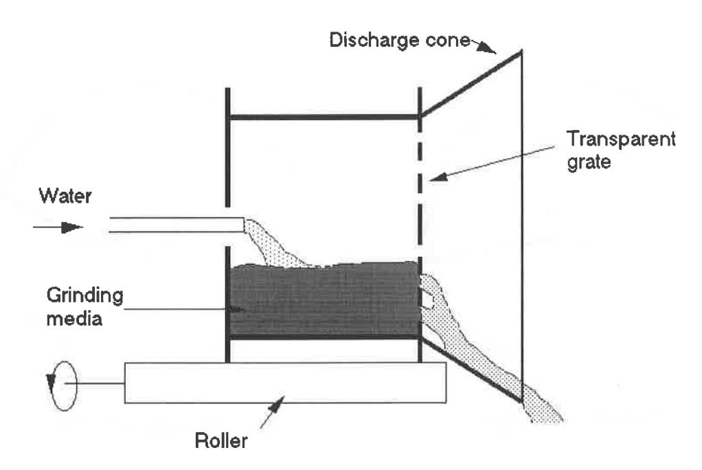
The equipment used in the testwork consisted of a 300mm X 160mm (DXL) laboratory scale mill using water only as the feed. A schematic view is shown in Figure 2. The feed water was fed through a 40mm pipe connected via a valve and rotameter for controlling and measuring the flowrate. The mill contained a vertically mounted grate made from 3mm thick clear perspex sheet which was divided into 16 panels. Holes were made at different radial positions to obtain an open area of 10% which was kept constant throughout. 6mm steel balls were used as the grinding media charge with a mill filling of 30% by volume. The discharge from the mill was collected through a launder.
Hold-up measurements were made by running the mill at the required feed flowrate at steady state, stopping the mill feed water and simultaneously collecting the mill discharge in a container. The water left inside the mill was then collected by draining it through a valve in the mill shell.
Scaled-down models of both radial and spiral type pulp lifters were made using 2mm thick clear perspex. A single pulp lifter segment representing 1/16th of the cross-sectional area of the mill was attached to one of the panels in the grate. Its discharge was collected independently through a separate launder. By multiplying this flowrate by 16 the equivalant flow for a full pulp lifter assembly was calculated.
Since the width of the pulp lifter ie its dimension measured parallel to the axis of rotation of the mill, determines it's load carrying capacity, the size of the pulp lifter was varied by changing this dimension. This was represented as a percentage of the mill length. The data so far collected from different industrial ag/sag mills shows that the width of the pulp lifter chamber normally varies in the range 3–10% of mill length.
The pulp lifter sizes used for this testwork were selected within this range and are given in Table 1.
|
Pulp lifter
size |
Percent of mill length |
|---|---|
| Small | 3.7 |
| Medium | 6.8 |
| Large | 9.9 |
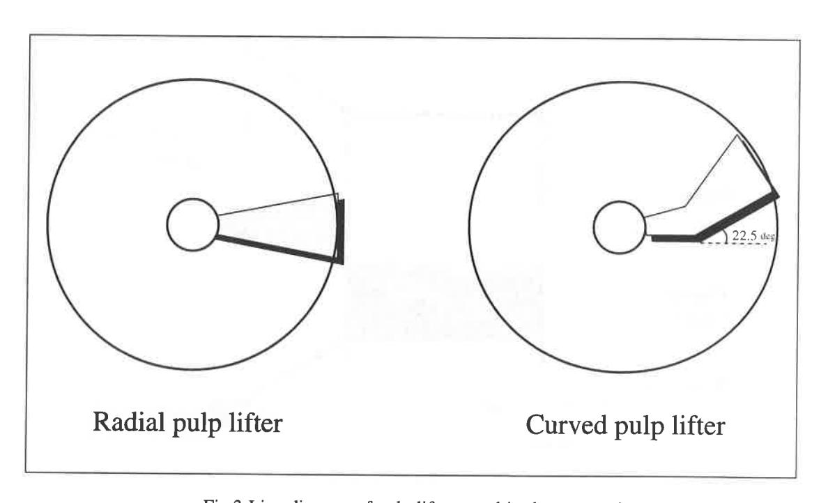
Tests were initially conducted using radial pulp lifters (Figure 3) at a range of mill speeds and feed flow rates. Subsequently, a scaled-down model of an ANI products pseudo-spiral type pulp lifter (Figure 3) was made and repeat tests were conducted to compare its performance with the conventional radial pulp lifters.
RESULTS AND DISCUSSION
Mill Hold-up Measurements
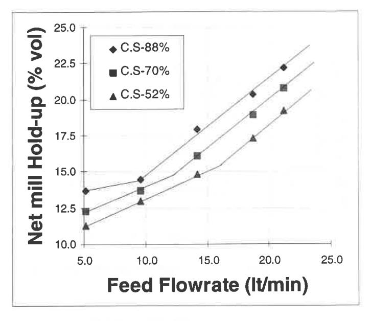
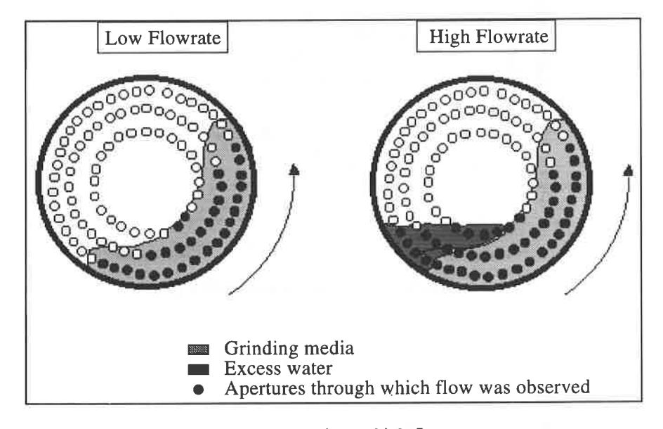
As expected, results obtained showed a progressive increase in hold-up with increasing flowrate. However, a distinct change in the gradient of the relation between flowrate and hold-up can be observed from Figure 4. The point at which the gradient changes occurs at different positions depending on the mill speed and is associated with the formation of a pool at the toe of the charge [6] as illustrated in Figure 5. It was also observed that the rate of increase in hold-up before pool formation was slower than the rate of increase in hold-up after pool formation. This may be attributed to the fewer grate holes per unit of hold-up volume in the pool area which were available for discharge compared to that in the area occupied by the charge.
Performance of the Pulp Lifters
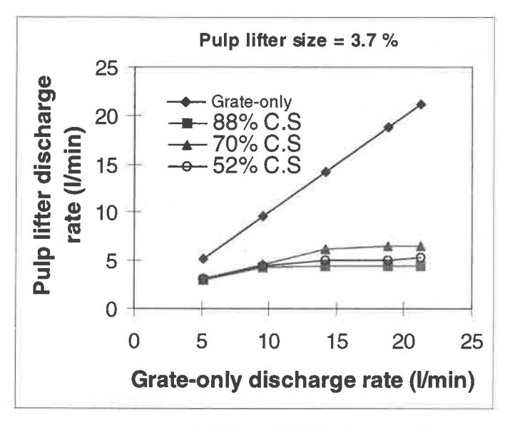
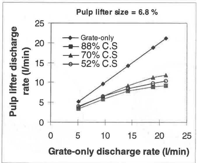
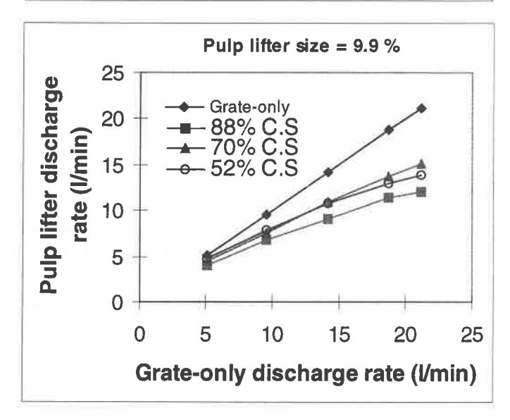
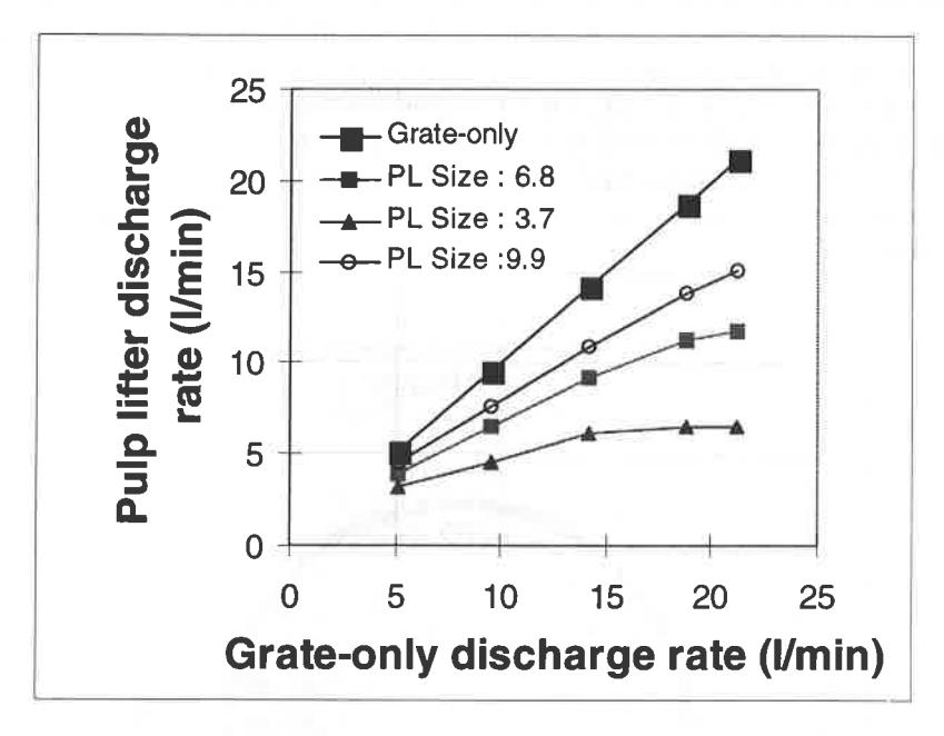
For ideal operation the discharge rate of the pulp lifters should be equal to the discharge rate of the mill operating only with a grate i.e. as an end discharge mill, at the same water hold-up. To compare the water removal performance of the pulp lifter with that of the grate, the discharge rate of the pulp lifters was plotted against that of the grate for the same water hold-up. It was found that the discharge rate of the pulp lifters was always significantly lower than the discharge rate of the grate as shown in Figure 6. The difference may be attributed to the following factors:
- 1. insufficient capacity of pulp lifters
- 2. flowback from the pulp lifter into the mill, and
- 3. carry-over inside the pulp lifter.
These processes can be summarised in schematic form as shown in Figure 7.
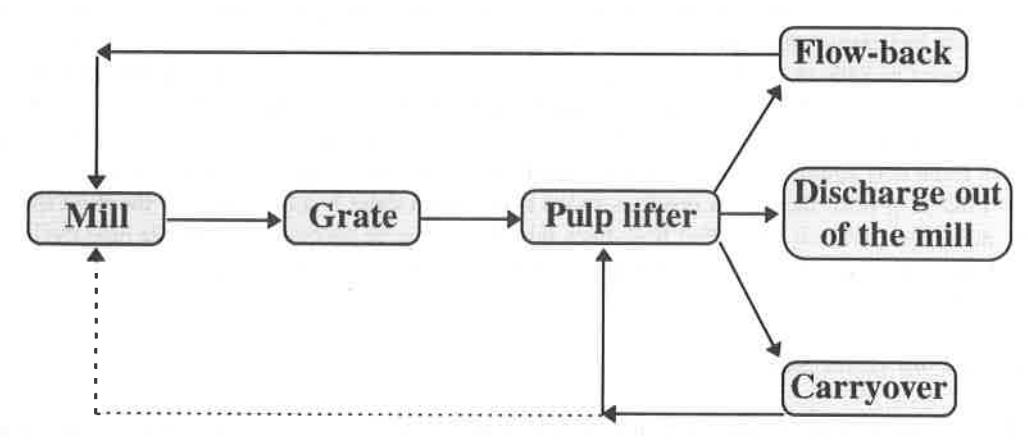
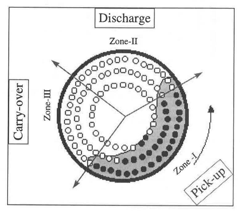
Flowback and carry-over can be illustrated by considering Figure 8 where the end of the mill is divided into three different zones. In every revolution of the mill, each grate/pulp lifter segment passes through all the zones. As the mill rotates in an anti-clockwise direction the charge and the water in the mill occupies the area in zone I which is typically between the 3 o'clock and 8 o'clock positions. Each segment of the pulp lifter first passes through zone I where water flows through the grate and accumulates in the pulp lifter chamber. As the mill rotates further the pulp lifter and the water contained in it are raised up to zone II where the water begins to flow down the radial face of the pulp lifter towards the centre of the mill where it is deflected towards the trunnion. However, once the grate/pulp lifter segment leaves zone I, the media charge and associated water will be no longer resting against the face of the grate inside the mill and hence the water in the pulp lifter tends to flow back into the mill via the same grate holes through which it entered. This phenomenon is called flowback . If the water inside the pulp lifter is not discharged completely before entering zone III, it is carried-over inside the pulp lifter. However, this is expected to occur only at higher mill speeds.
Influence of Mill Speed
It can be observed from Figure 6 that irrespective of the size of the pulp lifter, the discharge rate first increases with increasing mill speed up to 70% of critical speed (cs) and then reduces with a further increase of speed to 88% cs. This can be understood if one consider that, ignoring centrifugal force and at a constant mill hold-up, the rate at which the pulp lifters discharge and hence their capacity should be directly related to the mill rotational rate. However, as the rotational rate increases so does the centrifugal force. This force acts against gravity in zone-II where pulp lifter discharge occurs, and reduces the rate of flow down the pulp lifter face. As a result as speed is increased there is a tendency for the fluid to be held up in the pulp lifter where it will either flow-back into the mill or be carried over into the next cycle. There are, therefore, 2 opposing effects which result in a maximum discharge rate at a speed which is of the order of 70% of critical.
Influence of Pulp Lifter Size
Figure 9 shows the measured effect of changing pulp lifter width. It can be seen that at a given hold-up the discharge rate increased with increasing width of pulp lifter. It was also observed that each pulp lifter tended to a limiting capacity beyond which it was not possible to discharge further, regardless of the hold-up. In no case was it found that the pulp lifter discharge capacity matched that of the grate.
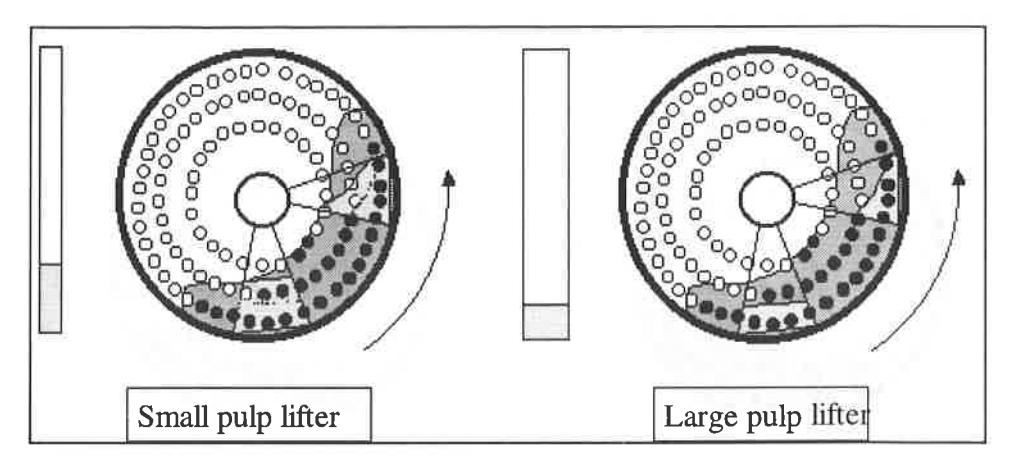
The improved performance of the pulp lifters with increasing size can be explained with the help of Figure 10 where it is illustrated that at a given flow through the grate the height of the water pool inside the pulp lifter reduces with increasing lifter width. This results in an increase in the pressure head across the grate hence allowing a higher flow through the grate whilst the pulp lifter is travelling through zone-I. At the same time the number of holes exposed for flowback is reduced when the pulp lifter enters zone II. This causes less flowback and more discharge into the trunnion for the same hold-up.
Tests with Spiral Pulp Lifters
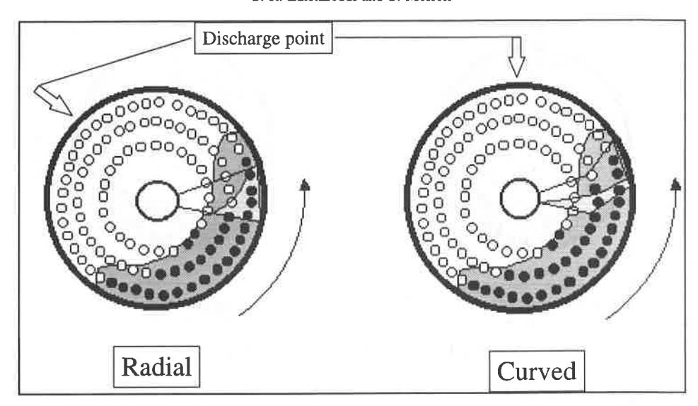
Although it has been claimed that spiral pulp lifters perform better than radial pulp lifters [1], there is no quantitative published data to support this assertion. Hence, a scaled-down model of a psuedo-spiral (curved) pulp lifter design was made whose volume was equal to that of the radial pulp lifters. Comparing the results obtained with these pulp lifters and the radial type, it was found that, irrespective of the test conditions, the discharge rate of the curved lifters was higher than the radial type as shown in Figure 11. However, the trends in the relation between flowrate and discharge rate remained the same. The increased capacity may be due to the faster discharge of water from the pulp lifter towards the trunnion [1]. Hence, with reference to Figure 12, at the horizontal position the water inside the radial pulp lifter has yet to discharge. However in the case of curved pulp lifters the water is already flowing towards the trunnion resulting in less flow-back and carryover.
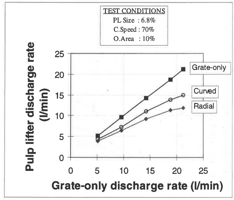
Despite the improvement in the flow capacity with the curved design their performance was also not found to match that of grate-only operation in the range tested and illustrates that they also do not operate in an ideal fashion.
Consequences of Poor Performance of Pulp Lifters
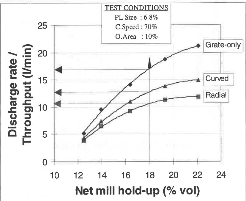
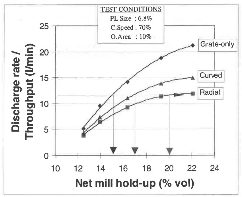
Two major disadvantages which are inevitable due to poor performance of pulp lifters can be observed from Figures 13a and 13b which show the relation between the slurry discharge rates and mill hold-up for different pulp lifters. These are:
- i. if the mill is operating at a certain hold-up level, the volumetric throughput of the mill when installed with either of the pulp lifters will be lower than the throughput which could be obtained with grate-only operation (Figure 13a).
- ii. if the mill has to operate at a certain flowrate, the hold-up in the mill will rise to a higher level than is necessary (Figure 13b). The increased hold-up in the mill may cause the mill to operate with a slurry pool, which causes a drop in power draw and a deterioration in milling performance [8].
CONCLUSIONS
On the basis of laboratory studies it has been found that over a wide range of pulp lifter sizes the rate at which slurry flows out of the pulp lifters is significantly less than that acheived with a grate-only discharge system. It is concluded that the capacity of pulp lifters in many cases is likely to represent the discharge rate-limiting step and therefore exert as much if not more influence than grate design on the flow capacity of mills. Apart from insufficient volume, the phenomena causing the difference in performance were flow-back and carry-over. Flow-back is the process in which slurry passes from the pulp lifter back into the grinding chamber. Carry-over occurs when slurry is not fully discharged from the pulp lifter.
ACKNOWLEDGEMENTS
The authors gratefully acknowledge the sponsors of the AMIRA P9L project for the financial support of this research.
REFERENCES
- Burgess, D., High or low aspect which one ?, in SAG Milling conference, edr. N.D.Stockton, Murdock University, 1989, pp. 132–170.
- 2. Mokken, A.H., Blendulf, G.K.I. & Young, G.J.C., A study of the arrangements for pulp discharge on pebble mills, and their influence on mill performance, J. South African IMM, May 1975, pp. 257–289.
- 3. Rowland, C.A. & Kjos, D.M., Autogenous and semi-autogenous mill selection and design, Australian Mining , September 1975, pp. 21–35.
- 4. Bond, F.C., History of autogenous grinding, SME Mineral Processing Handbook , Vol-1 , eds.N.L. Weiss, SME, New York, 1985, pp. 3c–57 3c–60.
- 5. Kjos, D.M., Wet autogenous mills, SME Mineral Processing Handbook , Vol-1 , eds.N.L. Weiss, SME, New York, 1985, pp. 3c-60 3c-7.
- 6. Morrell, S. & Stephenson, I., Slurry discharge capacity of autogenous and semi-autogenous mills and the effect of grate design, Int. J. Miner. Process. , 46(1-2), April 1996, pp. 53-72.
- 7. Strohmayr, S., Capacity limitations of pan lifter designs in grate discharge mills, B.E (Hon) Thesis, University of Queensland, Australia. 1994.
- 8. Morrell, S. & Kojovic, T., The influence of slurry transport on the power draw of autogenous & semiautogenous mills, in Proc. of Int. Conf. Autogenous and Semiautogenous Grinding Technology , Vancouver, B.C., 1996, pp. 378–389