



The content on this page was automatically generated from the PDF publication document and may contain errors or inaccuracies. Please refer to the original PDF for the most accurate information.
A New Design of Pulp Lifter for Grate Discharge Mills
S R Latchireddi1 and S Morrell1
ABSTRACT
As more and more autogenous and semi-autogenous mills are run in closed circuit with cyclones the limitations that can be imposed by poor grate and pulp lifter design are becoming increasingly apparent. Relevant literature on the subject is almost non-existent. Hence a research program was initiated at the Julius Kruttschnitt Mineral Research Centre (JKMRC) to study the behaviour of grate and pulp lifter discharge systems.
Experiments were carried out in a laboratory SAG mill with scale models of conventional pulp lifters to assess their performance in terms of their discharge capacity. The variables that have been studied are size and design of pulp lifter, open area of grate apertures and their location, as well as mill speed and charge volume.
This paper presents the results of these experiments which show that conventional pulp lifter designs which have insufficient volume will provide severely limited flow capacity. The main factor which contributes to this relatively poor performance is flow-back of slurry from the pulp lifter into the mill. The cause of this phenomenon is described in the paper together with a new design of pulp lifter which has been developed at the JKMRC called the 'Twin Chamber pulp lifter' (TCPL). This new design largely eliminates flow-back. The performance of the TCPL relative to conventional pulp lifters is described.
INTRODUCTION
The continuing trend of building larger and larger diameter autogenous and semi-autogenous mills has brought into focus the importance of correct design of the pulp lifter assembly. The main function of the pulp lifters is to transport the slurry, which flows through the grate holes, out of the mill via the discharge trunnion.
A schematic of the cross-section of a typical ag/sag mill with a grate/pulp lifter discharge mechanism is shown in Figure 1a. As the mill rotates each grate/pulp lifter segment passes through the slurry pool where the slurry flows through the grate and accumulates in the pulp lifter chamber. With further rotation of the mill the pulp lifter and its slurry contents are raised and the slurry begins to flow down the radial face of the pulp lifter towards the centre of the mill as depicted in Figure 1b. The
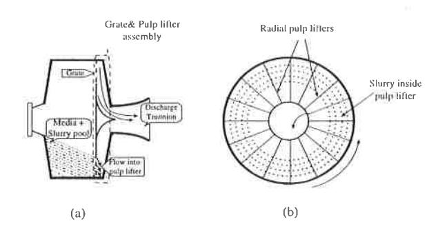
Julius Kruttschnitt Mineral Research Centre, Isles Road-Indooroopilly Qld 4068. slurry is deflected at this point so it flows through the trunnion and out of the mill.
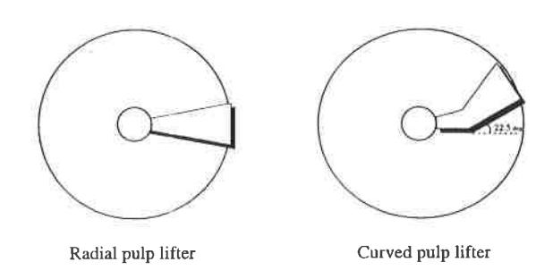
There are typically two types of pulp lifters that are used in industry:
- · radial, and
- curved.
Of the above two designs, the radial type pulp lifters are the most commonly used ones in the minerals processing industry.
Although pulp lifters have been in use since the inception of grate discharge mills (Robinson 1980), very little research has been conducted/reported on the effect of grate and/or pulp lifter design on slurry flow through the mill. Mokken et al 's work (Mokken et al , 1975) is the first to mention some of the possible drawbacks of pulp lifter discharge mechanisms, such as flowback or short circuiting of slurry from the pulp lifters into the mill and higher pulp levels inside the mill. However, no quantitative result were reported. A single scoop enclosed lifter was tried as a possible alternative but no improvement in mill performance was observed.
In 1975, Rowland and Kjos stated that, for a successful mill operation, the load carrying capacity of pulp lifters is perhaps more important than the grate slot area. A decade later both Bond (1985) and Kjos (1985) reiterated the importance of pulp lifter assembly design and stated that the problem associated with them had yet to be solved. However, comparing the discharge mechanism in both radial and spiral pulp lifters, Burgess (1989) mentioned that the latter allowed slurry to discharge more quickly and so avoided the risk of carry over. He also claimed an increase in grinding efficiency with spiral pulp lifters
As more and more autogenous and semi-autogenous mills are run in closed circuit with cyclones the limitations that can be imposed by poor grate and pulp lifter design are becoming increasingly apparent. As mentioned above, relevant literature on the subject is almost non-existent. Hence a research program was initiated at the Julius Kruttschinutt Mineral Research Center (JKMRC) to study the behavior of grate and pulp lifter discharge systems. Under this program, the authors have carried out a set of preliminary experiments in a laboratory SAG mill to understand the performance of conventional pulp lifters in terms of discharge rates. Based on the preliminary test results it has been found that over a wide range of pulp lifter sizes the rate at which slurry flows out of the pulp lifters is significantly less than that achieved with a grate-only system and has been attributed mainly to flow-back and carry-over phenomena.
To overcome the problems associated with conventional pulp lifters, a new design called the Twin Chamber Pulp Lifter (TCPL) has been developed and patented. This paper illustrates the advantages of the TCPL over conventional designs along with a brief description of the cause of the problems associated with conventional pulp lifter design.
EXPERIMENTAL
Tests were carried out in a laboratory scale mill of 300 mm x 160 mm (DXL) size using water only as the feed. The experimental set-up of the mill used in the testwork is shown in Figure 2.
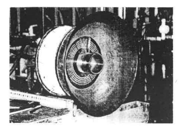
The feed water was fed through a 40 mm pipe connected via a rotameter for controlling the feedrate. The grate used in the testwork was vertically mounted and was made of 3 mm thick clear perspex sheet which was divided into 16 panels. Holes were made at different radial positions and their size was varied to obtain the required fractional open area. Six millimetre steel balls were used as the grinding media charge. The discharge from the mill was collected through a launder.
A single pulp lifter segment was attached to one of the panels on the grate. The discharge from the pulp lifter was collected via a separate launder. The discharge rate of the one pulp lifter segment was multiplied by the total possible number of pulp lifters (16) to obtain the actual discharge capacity of an entire pulp lifter assembly. For every test the water held-up inside the mill was measured. This arrangement allowed a simultaneous flowrate measurement to be made of a grate-only and a pulp lifter assembly under identical hold-up conditions.
For a range of pulp lifter designs, tests were carried out by varying the pulp lifter size, feed flowrate, mill speed to understand their influence on pulp lifter performance.
For a given mill configuration the capacity or size of the pulp lifter can be varied essentially by changing its width as measured along the axis of the mill. Hence the size of the pulp lifter in this paper is represented as the per cent ratio of the pulp lifter width to the mill length [Per cent ratio = (Pulp lifter width/mill length)*100]. Data from different industrial ag/sag mills show that the width of the pulp lifter chamber varies in the range three - ten per cent of mill length. Hence for the laboratory mill a similar range was selected. The details are given below.
| Pulp lifter size | Small | Medium | Large |
|---|---|---|---|
| Per cent ratio | 3.7 | 6.8 | 9.9 |
IDEAL PERFORMANCE OF PULP LIFTERS
In an end-discharge mill with a grate-only assembly, the feedrate will be equal to the discharge rate at steady state. Corresponding to this condition a certain volume of slurry will be held up inside the mill largely due to the resistance offered by the grate. For this system, suppose the relation between the mill hold-up and the discharge rate appears as shown in Figure 3.
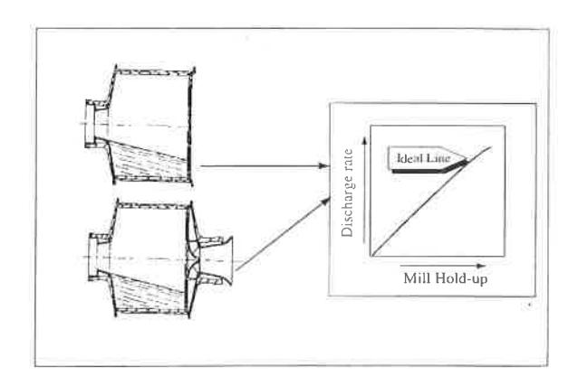
If a pulp lifter assembly is fixed on to the mill then under ideal conditions the discharge rate of the grate and pulp lifter assembly at a given mill hold-up should be equal to the discharge rate obtained with the grate-only system. Hence a similar plot of hold-up vs discharge rate should be obtained. If the pulp lifter assembly restricts flow then the hold-up vs discharge rate relation will deviate from the grate-only plot. The grate-only relationship can be considered as the ideal condition.
PERFORMANCE OF CONVENTIONAL PULP LIFTER DESIGNS
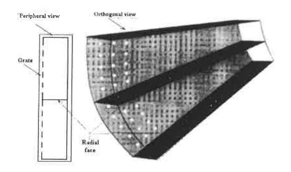
Scaled-down models of two types of conventional pulp lifter designs as shown in Figure 4 were used in the test work. The pulp lifters were made using 2 mm thick clear perspex.
To assess the slurry removal performance of the pulp lifter with reference to the ideal or grate-only discharge system, the discharge rate of the pulp lifters were plotted against the mill hold-up values. It was found that the discharge rate of the pulp lifters was always significantly lower than the discharge rate of the grate-only system at any given mill hold-up value.
It may be noted from Figure 5, that even when the size of the pulp lifter was increased considerably the discharge rate of radial pulp lifters did not reach the ideal relation. The smaller size pulp lifter can be seen to have substantially lower capacity than the ideal.
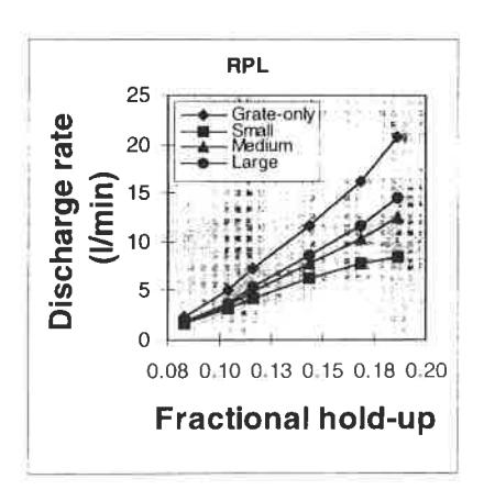
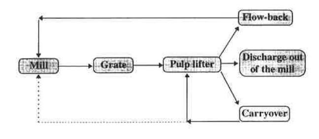
Irrespective of the pulp lifter size, the significant difference in the discharge rates may be attributed to the factors given below (Latchireddi and Morrell, 1997).
- flow-back from the pulp lifter into the mill, and
- · carry-over inside the pulp lifter.
The schematic representation of the above processes is shown in Figure 6 and is further illustrated in Figure 7.
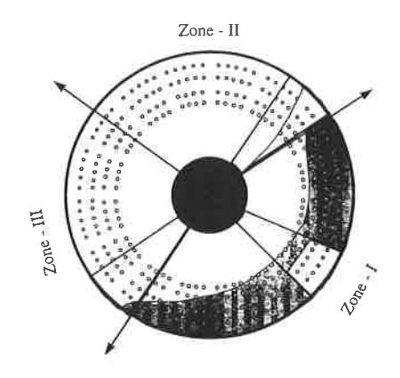
In every revolution, each segment of the pulp lifter does three different operations as shown in Figure 7. As the mill rotates in an anti-clockwise direction the charge and the water in the mill typically occupies the area in Zone I. Each segment of the pulp lifter first passes through Zone I where water flows through the grate and accumulates in the pulp lifter chamber. As the mill rotates further the pulp lifter and the water contained in it are raised up to Zone II where the water begins to flow down the radial face. However, once the grate/pulp lifter segment leaves Zone I, the media charge and associated water will be no longer present against the face of the grate inside the mill and hence the water in the pulp lifter tends to flow back into the mill via the same grate holes through which it entered. This phenomenon is called flow-back. If the water inside the pulp lifter is not discharged completely before entering Zone III, it is carried-over to the next cycle. However, this is expected to occur only at higher mill speeds.
The improved performance of the pulp lifters with increasing width can be explained by considering that at a given flow through the grate the height of the water pool in the pulp lifter reduces proportionately with increasing pulp lifter width. This reduced height inside the pulp lifter increases the head across the grate and at the same time reduces the number of holes exposed for flow-back when the pulp lifter enters Zone II, resulting in a higher discharge rate.
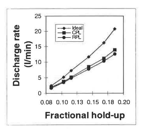
Compared to that of a radial pulp lifter, the curved pulp lifter gives higher discharge rates at a given mill hold-up (Figure 8) which is due to the faster discharge of water from the pulp lifter towards the trunnion. However, the discharge rates of these lifters were also not found to match those of a grate only assembly.
Consequences of poor performance of pulp lifters
Though the curved pulp lifters perform better than radial pulp lifters, there are two major disadvantages which are inevitable due to their poor performance. They are, compared to the grate-only discharge system,
- lower volumetric throughput of the mill at a given mill holdup, and
- higher level of slurry inside the mill due to flow back which may result in pool formation inside the mill thus reducing the power draw and possibly grinding performance (Morrell and Kojovic, 1996).
Based on the above observations, it is essential to reduce the flow-back process as much as possible to improve the performance of the pulp lifters. This may be possible by increasing the width of pulp lifter to such an extent that the slurry inside the pulp lifter is not exposed to the grate holes/slots. However, this may increase the cost of the mill. This prompted the design of a new pulp lifter called the Twin chamber pulp lifter.
DEVELOPMENT OF TWIN CHAMBER PULP LIFTER (TCPL)
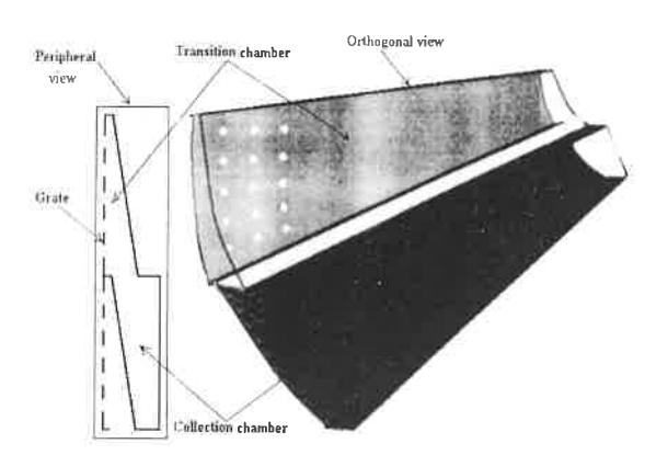
The only way to stop flow-back is to ensure that the slurry, once it has entered pulp lifter, is not exposed to the grate holes/slots. In order to achieve this, the two contiguous segments of a radial pulp lifter were considered (Figure 9) and, following the steps illustrated in Figure 10, the new design was developed (Figure 11).
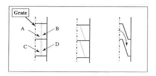
It can be seen from Figures 10 and 11 that the pulp first enters the section exposed to the grate which is called the Transition chamber and can then flow into the lower section called the Collection chamber which is not exposed to the grate. Hence, it is unable to flow backwards and flow-back can be prevented to a great extent.
Performance of twin chamber pulp lifter
Tests were conducted under identical conditions with a prototype perspex model of a TCPL whose volumes were equal to those of the radial pulp lifters (RPL). The discharge rates of the TCPLs are plotted against the mill hold-up as shown in Figure 12.
On comparing Figure 12 with Figure 5, the following points may be observed
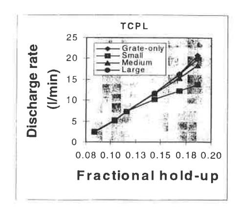
- the TCPL performance matches with that of a grate-only system over a much greater range of flowrates.
- Increasing pulp lifter size increases the discharge rate and hence the range over which it matches ideal discharge rates.
- The point where the discharge lines deviate from the ideal line indicates that the volume of water flowing into the pulp lifter through the grate exceeds the capacity of the collection chamber. Hence part of the water remains held-up in the transition chamber, which then performs in a similar manner to that of RPL.
The above observations clearly demonstrates that the flow-back process can be eliminated, up to the capacity of the collection chamber, by using a TCPL.
COMPARISON OF PULP LIFTERS
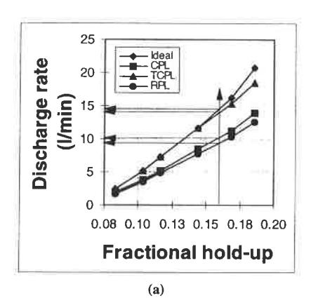
To illustrate the superiority of TCPL over conventional pulp lifter designs, the relationship between the hold-up and discharge rates of the TCPL, RPL and CPL are plotted for a particular condition as shown in Figure 13.
It may be noted from the above figures that for the same pulp lifter size:
- At a given level of water in the mill, the discharge rate of the TCPL is much higher than that of RPL (Figure 13a). It is obvious from this that for the same level of water in the mill, the mill can be operated at a higher throughput with the TCPL than with the RPL and CPL.
- At a given feed flowrate, the mill hold-up (level of water in
the mill) is very close to the grate-only hold-up when the TCPL is used (Figure 13b), whereas when the RPL is used, the mill hold-up increases to a higher level due to flow-back. This can inhibit the grinding efficiency by running the mill too wet.
Hence, compared to RPL, using TCPL is advantageous in maintaining slurry levels nearer to the ideal conditions which may result in better grinding performance.
CONCLUSIONS
The testwork carried out so far in the laboratory mill leads to the following conclusions.
- Though the CPL design performs better than the RPL, both these designs have some inherent drawbacks which results from flow-back and carryover processes.
- The TCPL design overcomes most of the problems associated with conventional designs. This results in the operation of the mill very close to the grate-only condition in terms of mill hold-up and volumetric throughput.
- The TCPL can be precisely designed to handle the required volumetric throughput.
REFERENCES
- Bond, F. C. 1985. History of autogenous grinding, SME Mineral Processing Handbook (Ed: N. L. Weiss) Volume-1, SME, 1985, Newyork: 3c-57 3c-60.
- Burgess, D. 1989. High or low aspect which one?, SAG Milling Conference (Ed: N D Stockton) pp 132-170 (Murdoch University).
- Kjos, D M, 1985. Wet autogenous mills, SME Mineral Processing Handbook (Ed: N L Weiss) Volume-1, SME, 1985, Newyork: 3c-60 - 3c-75.
- Latchireddi, S R and Morrell, S, 1997. A laboratory study of the performance characteristics of mill pulp lifters, Minerals Engineering (in press)
- Mokken, A H, Blendulf, G K I and Young, G J C, 1975. A study of the arrangements for pulp discharge on pebble mills, and their influence on mill performance, J South African IMM, May:257-289
- Morrell, S and Kojovic, T, 1996. The influence of slurry transport on the power draw of autogenous & semiautogenous mills, Proc of Int Conf Autogenous and Semiautogenous Grinding Technology, Vancouver, BC, pp 378-389.
- Robinson, B. 1980. The History of autogenous grinding, CIM Bulletin, October:114-118.
- Rowland, C A and Kjos, J M, 1975. Autogenous and semiautogenous mill selection and design, Australian Mining , September:21-35.