



The content on this page was automatically generated from the PDF publication document and may contain errors or inaccuracies. Please refer to the original PDF for the most accurate information.
Charge Motion in Tower Mills
by M. S. Duffy & S. Morrell
Senior Plant Metallurgist, Mount Isa Mines, Mount Isa, Queensland
Manager, Comminution Research, Julius Kruttschnitt Mineral Research Centre, University of Queensland
ABSTRACT
To exploit the mineral resources of fine grained ore bodies the minerals processing industry is turning to fine grinding technology, of which tower milling has become an established part. However, compared to other mills relatively little is known about the operating mechanisms in tower mills. In all milling processes one of the keys to understanding how they work is in knowing how their grinding media move. To investigate the ball motion in tower mills a glass unit was therefore constructed and measurements taken of the movement of the grinding media. This paper describes the results from this study.
INTRODUCTION
The rate at which particle breakage occurs in a tower mill is related to the number, size and weight of the grinding media used and to their motion which is imparted by the helical screw. How the media move determines the mode with which particles are broken within the mill. Being able to understand the fundamental mechanisms by which grinding takes place in a tower mill is the first step to modelling the process. To this end, a fully scaled model transparent tower mill was designed and built at the JKMRC to investigate the grinding media flow patterns occurring in these mills. Quantitative and qualitative methods were used to determine the ball movement in the mill which was run under a wide range of operational conditions.
TEST EQUIPMENT
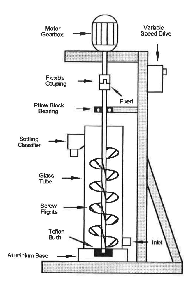
A schematic diagram of the transparent tower mill used during the testwork is depicted in Figure 1. The drive comprised an integral motor/gearbox which was rated at 0.25 kilowatts and had a top speed of 115rpm. A variable speed drive was used to control the motor speed. The agitator was a double start right hand helical screw stirrer. The stirrer had a screw diameter to screw pitch (vertical distance between individual screw flights corresponding to one turn of the screw) ratio of 1:1. The agitator was supported on a centred nylon bush sunk into an aluminium base. The drive shaft was connected to the motor shaft by a flexible coupling. A pillow block bearing was used to support the drive shaft. The grinding media were spherical glass balls. Two sizes were used: 3mm and 5mm.
BALL VELOCITY DETERMINATION
To observe the workings within the mill it was necessary to make the ball charge transparent. This was achieved by manipulating the refractive index of the liquid phase to match that of the glass. As the glass balls within the grinding chamber subsequently became invisible, coloured glass tracers were used to highlight and measure the media motion. Measurements of the velocity of the media at different locations were made from still photographs of the mill using a slow shutter speed. The resultant photographs showed lines of colour associated with the movement of the tracers, the length of each line being proportional to their speed. The length of each line was measured and subsequently converted into velocities.
In industrial mills steel balls are normally used to grind slurries which have viscosities higher than those used in these experiments. As a result, the coefficient of friction between balls and the frictional forces experienced may be different. It is therefore expected that the absolute velocities of grinding media in different systems will vary. The trends, however, should be similar.
EXPERIMENTAL RESULTS
Experiments were focused on determining what effects certain operating variables have on the ball movement within the tower mill. The variables investigated were stirrer speed, ball size and flowrate.
Ball Charge Motion
The ball motion within the tower mill is a direct result of the rotating and lifting action generated by the helical screw. From photographic techniques and observations made from high speed videos, the ball movement experienced in the mill is schematically represented in Figure 2.
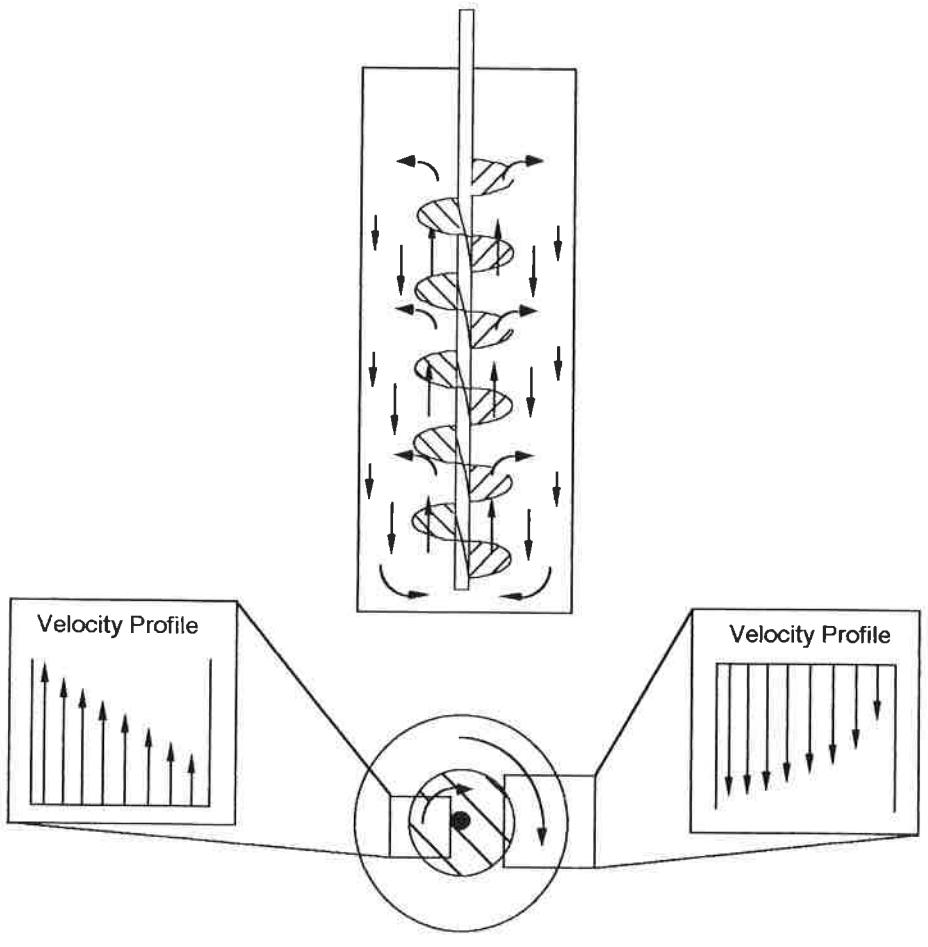
All the experiments performed showed that the ball motion occurred as a rotating packed bed up until the onset of fluidization. No bed dilation therefore occurred providing the upward flow of fluid in the mill was below fluidization levels. As depicted from Figure 2, the balls within the central screw column (from shaft to stirrer tip) were carried upwards on the screw flights at a specific radial position. This rotating charge ascends the screw column at an angle of 45° to the horizontal ie the same angle as the screw. When the grinding media neared the top of the charge, they were dispersed towards the outer mill wall. From here, the grinding media spiralled downward within the outer annular region (stirrer tip to mill wall), again holding their radial position. The media in this vicinity did not migrate downward at a constant angle. From detailed observations obtained from high speed video, it was seen that grinding media closer to the helical screw travelled down the annular region at steeper gradients than the media near the mill shell. The angle of descent of the grinding media within a few ball depths from the mill wall was measured at 33° to the horizontal.
"Leakage" of particles across the interface between the screw column and the outer annular region was also observed from the high speed videos. The occurrence of this though was quite small. The ball flow pattern schematically represented in Figure 2 occurred for all ball sizes and all stirrer speeds up until the stirrer speed where centrifuging of the charge took place. At this speed and beyond, the ball charge began to rotate as a single mass (see later).
Due to the fact that the grinding media rotated as a packed bed within the tower mill, little radial movement was observed. The only radial velocity occurring in the mill was found at the top and bottom of the grinding chamber and through the leakage of balls from the stirrer tip to the outer annular region.
From the motion observed in the mill, attrition was seen to be the principle mode of breakage. This occurred mainly in the outer annular region. In this region, grinding media were seen to be sliding and rolling over one another which is indicative of attrition breakage conditions. The grinding media on the screw were found to move largely en-masse, with some slip at the surface of the screw and therefore little breakage would be expected to take place in this region.
Tangential Velocity Profiles
A schematic representation of the observed tangential velocity profile as viewed in plan is depicted in Figure 3.
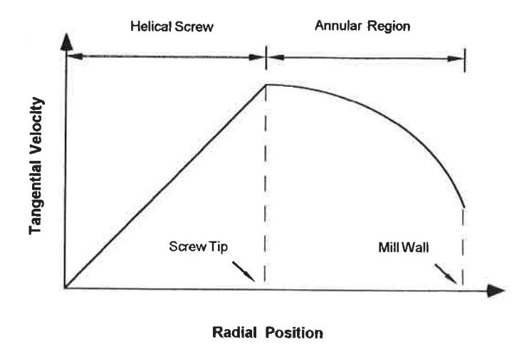
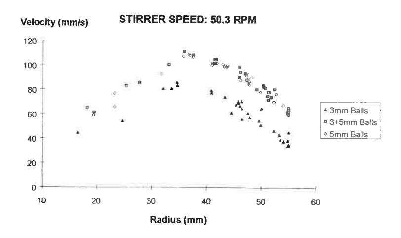
From this diagram, the most noticeable feature is the point at which the maximum ball velocity occurs at the stirrer tip. This was expected since, as the balls move en-masse in the stirrer column, balls at the tip of the helical screw should have the highest tangential velocity and be a linear function of their radial position. Measurements showed this to be the case. this caused
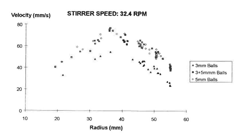
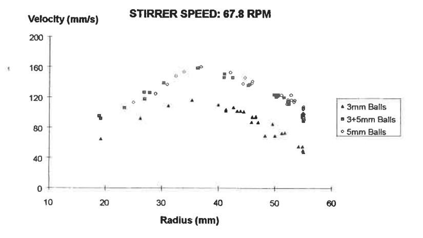
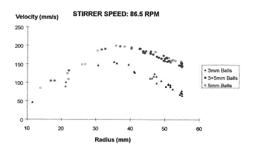
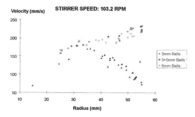
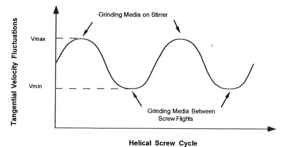
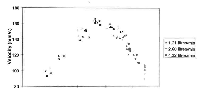
Velocity profiles in the outer annulus were mostly seen to decrease from a maximum at the stirrer tip to a minimum at the mill wall. This reduction in velocity was due to the drag exerted by the mill wall which was transferred via contiguous layers of balls. This caused slippage between ball layers, the degree of slip between each layers being dependent on the coefficient of friction and the bed pressure. Tangential velocity profile results from the tests for each stirrer speed and ball size are shown in Figure 4. Some scatter is seen and is indicative of the motion imparted by the screw on the ball charge. The screw produces a cyclic motion on the grinding media in which they travel at different speeds depending on their position relative to the screw surface. Due to the shape of the stirrer the grinding media in the outer annulus have a minimum and a maximum proximity to the screw surface as the screw rotates. At the point of nearest approach the media travel at their maximum velocity whilst at the point of furthest approach the velocity is at a minimum. Therefore, in a given position the media velocity with respect to time follows a wave form (Figure 5) with an amplitude of the order of 10-15mm/s. The scatter observed in the velocity profile measurements is largely due to this phenomenon.
a)
b)
d)
e)
Flowrate Effects
Within the range tested, the flowrate of the liquid being pumped into the glass tower mill was found to have no effect on the ball motion for all stirrer speeds, regardless of ball size. This is illustrated in Figure 6. As the flowrate approaches and exceeds that required to induce fluidization of the ball bed it is expected that media flow will change dramatically. All flowrates used during this ball motion study were less than 40% of that required for fluidization.
STIRRER SPEED: 67.8 RPM
Radius (mm)
Ball Size Effects
Ball size effects on the tangential velocity profiles were pronounced. As can be seen in Figure 4 the velocity of the 3mm balls was significantly lower than that of the 5mm ones. This is explained by the fact that, due to the larger number of smaller balls per unit volume, the pressure exerted at contact points between balls is less and hence so is the frictional force. More slip results, causing a greater loss in velocity between contiguous layers. This phenomenon was confirmed by power draw measurements which showed that smaller ball sizes were found to draw less power for the same mass (Table 1). Interestingly the mix of 3mm and 5mm balls moved in a similar manner to the 5mm charge, indicating that the larger balls dominated the charge motion.
| Ball Size | Stirrer Speed (rpm) | ||||
|---|---|---|---|---|---|
| 32.4 | 50.3 | 67.8 | 86.5 | 103.2 | |
| 3mm | 5.0 W | 10.41 W | 14.68 W | 19.74 W | 25.13 W |
| 5mm | 8.21 W | 13.88 W | 18.63 W | 22.88 W | 27.07 W |
Helical Screw Stirrer Speed Effects
The helical screw stirrer speed had a significant influence on ball motion. Increasing the stirrer speed increased the tangential velocities of the glass balls in both the screw column and outer annulus regardless of ball size (Table 1). In relation to the grinding media within the screw column, this increase was seen to be a linear one. By increasing the speed of the stirrer two fold, the ball velocities in this region doubled. In all but 1 case the same trend was apparent in the velocities in the outer annulus. The same trend was also observed in the power measurements obtained from the mill.
Results from the highest speed test show an interesting departure from the trends observed at lower speeds. For the 5mm ball charge the velocity in the outer annulus was not observed to fall off but continued to increase with radial position. This implied that the charge in the outer annulus was rotating at the same rate as that in the stirrer column ie it was centrifuging. It is postulated that in this case the centrifugal force generated in the outer annulus was such that slip between contiguous layers was avoided. As the 3mm balls travelled at lower velocities the centrifugal force generated was insufficient to halt slip and hence the velocity profile observed at lower stirrer speed was maintained.
CONCLUSIONS
Particle breakage in the tower mill has been seen from the observed grinding media flow patterns to be primarily caused by attrition, attrition being the process of particle breakage which occurs between grinding media sliding and rolling over one another. No impact motion was observed.
The action of the stirrer was observed to be one of simultaneously lifting the mill charge to the top of the screw and rotating it in a packed bed as it descended in the outer annulus. The tangential velocity of balls within the screw column was found to be similar to that of the screw. Beyond the screw tip the ball velocity was normally found to reduce progressively, reading a minimum at the mill wall. Only at very high speeds was centrifuging noticed at which point the entire ball charge rotated en masse.
This motion of grinding media within the tower mill was found to be influenced by variables, namely stirrer speed and ball size.
- Increasing the stirrer speed increased the tangential velocities of all the grinding media.
- Ball size was also shown to greatly influence the motion of grinding media in the tower mill. The tangential velocity was found to decrease as ball size was reduced, increase in slippage between adjacent balls being the major cause.
- Flowrates below that required to cause fluidization were found to have no effect on the media motion in the tower mill.
ACKNOWLEDGMENTS
The financial assistance from the sponsors of the AMIRA P336A Project (Methods and Benefits of Fine Grinding) is gratefully acknowledged.
REFERENCES
- Duffy, M. S. 1994. Investigation into the performance characteristics of tower mills. University of Queensland Masters Thesis.
- Tipler, P. A. 1982. Physics. Worth Publishers Inc. New York, 2nd ed., pp 847-876.
- Sax, N. and Lewis, R. (Sr), 1987. Hawleys' Condensed Chemical Dictionary. Van Nostrand Reinhold Company Inc., New York, 11th ed.