



The content on this page was automatically generated from the PDF publication document and may contain errors or inaccuracies. Please refer to the original PDF for the most accurate information.
COPPER CONCENTRATOR AUTOGENOUS GRINDING PRACTICES AT MOUNT ISA MINES LIMITED
- J. Karageorgos', B. Burford2, W. Valery Jr.3, P. Rohner', N. W. Johnson2, S. Morrel13
- 1- Copper Concentrator, 2- Metallurgical Development, Mount Isa Mines Limited, 3- Julius Kruttschnitt Mineral Research Centre, Brisbane, Australia.
ABSTRACT
In the copper concentrator, a traditional crushing and primary grinding circuit was replaced by two autogenous grinding mills (9.8m diameter x 4.4m length) in June 1991.
These mills were originally designed to operate in open circuit or with four 690 mm inclined hydrocyclones in closed circuit. Each autogenous mill was also planned to be followed by one ball mill in closed circuit with six 508 mm vertical hydrocyclones. After commissioning, the autogenous mills had to be operated in open circuit to meet the design throughput of 400 tph. Closed circuit operation resulted in a severe throughput reduction, decrease in power draw and over-grinding. This highlighted an accumulation of slurry and a fundamental slurry transport limitation within the mills.
The resulting flotation feed size was changed from a p, (80% passing size) of 150 microns (original crushinglgrinding circuit) to a p,, of 100 microns (autogenous mills in open circuit). Liberation and flotation studies have shown no significant benefits of a finer flotation feed.
This paper describes the evolution of the grinding circuit and results of test work conducted by Mount Isa Mines Limited (MIM) in collaboration with the Julius Kruttschnitt Mineral Research Centre (JKMRC) to study circuit alternatives and the effect of operating variables to achieve maximum performance from the autogenous mills.
Maximising the performance of the autogenous mills will possibly enable the removal of one secondary ball mill, further simplifying the grinding circuit whilst maintaining the current production budget of 6.0 Mtpa (million tonnes per annum). This will result in a flotation feed with a p, of approximately 170 microns, which is slightly coarser than the original crushinglgrinding circuit which produced a flotation feed with a p,, of 150 microns. If successful, this project would result in savings of approximately A$ 3.0 million per annum (1 996 dollars).
INTRODUCTION
In the copper concentrator, a traditional crushing and primary grinding circuit was replaced by two autogenous grinding mills (9.8m diameter x 4.4m length) in June 1991.
Since then different autogenous grinding practices have been explored and valuable operational experience has been acquired. Test work has been conducted by MIM in collaboration with the JKMRC to study circuit alternatives and the effect of operating variables to achieve maximum performance from the autogenous mills.
This paper presents some of the acquired plant experience and the main results of test work and simulation studies since the installation of the autogenous mills.
GRINDING CIRCUIT DESCRIPTION
Although this paper concentrates on the autogenous grinding practices at the copper concentrator, a brief description of the original crushinglgrinding circuit is presented to give a complete view of the history and evolution of the grinding circuit to date.
The copper concentrator was originally commissioned in May 1973. Since then, it has been treating chalcopyrite ore from the upper ore bodies of the mine (1 100 and 1900 series), as well as the deep copper ore body (3000 series), at a rate of 6.0 Mtpa.
It has also been treating approximately 0.1 million tonnes of slag per annum from the copper converters, the copper being in the form of diginite (Cu,,, S).
Until June 1991, the original crushinglgrinding circuit had remained relatively unchanged. Ore was crushed by underground jaw crushers with gap settings of 150 mm and hoisted to the surface. The ore was stored in a crude ore bin and conveyed to the copper concentrator crushing circuit. The crushing circuit consisted of two scalping screens (65 mm square slots), two primary Symons standard cone crushers (2.13 m diameter), four screens (13 mm x 25 mm slots) and three secondary Symons short head crushers (also 2.13 m diameter) in closed circuit with screens (13 mm x 25 mm slots). The primary and secondary crushers were driven by 224 kW motors.
The ore was then transported by a system of conveyor belts into a fine ore bin, from where it fed two identical lines of grinding. Each line consisted of a rod mill (3.8 m diameter x 5.5 m, 11 00 kW motor) in open circuit, followed by a primary ball mill in closed circuit with 508 mm vertical hydrocyclones and a secondary ball mill also in closed circuit with 508 mm vertical hydrocyclones. All ball mills were identical (5 m diameter x 6 m, 2600 kW motor). The flotation feed size produced from this circuit had a p,, of approximately 150 microns. A schematic of the original crushinglgrinding circuit is shown in Figure 1.
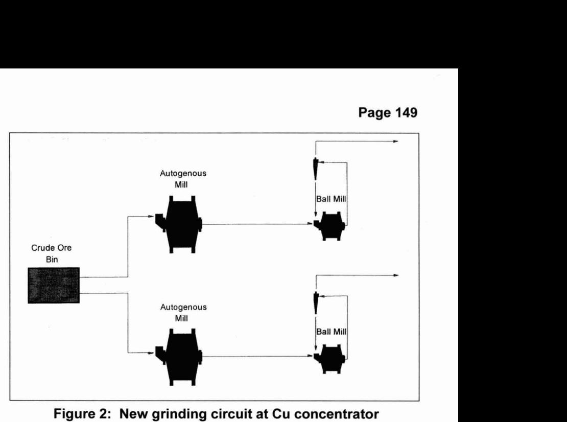
In June 1991, the primary and secondary crushers as well as the rod mills and primary ball mills were replaced by two 9.8 m diameter x 4.4 m Boliden-Allis Chalmers autogenous mills. Each of the autogenous mills was driven by two 3.2 MW motors (ie. 6.4 MW per mill).
The total installed power of the new grinding circuit was 18 MW (12.8 MW on primary grinding and 5.2 MW on secondary grinding), compared to the original crushinglgrinding circuit which was 13.7 MW (1.1 MW on secondary crushing, 2.2 MW on rod milling, and 10.4 MW on ball milling).
The gap setting of the underground jaw crushers was increased from 150 mm to 250 mm. The crushed ore was then transported by conveyor belts to the existing crude ore bin (50,000 tonnes live capacity). The existing parallel feeder and conveyor system had to be modified to receive the coarser ore and transfer it to the autogenous mills.
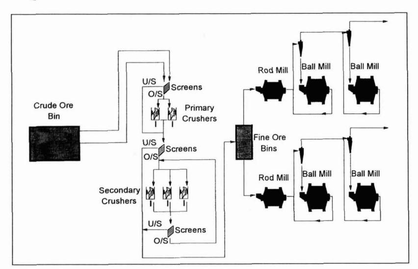
The installation of the autogenous mills reduced the operation and maintenance costs by A$ 9.8 million per annurn (1991 dollars) and deferred A$ 5.0 million capital (1991 dollars) that was required for refitting the crushers (Leung et al., 1992). The number of conveyors in the plant decreased from twenty-seven to two. A crusher building containing five crushers and three sets of screening and associated equipment was made redundant. Transfer towers, fine ore bins, two rod mills and two ball mills and other equipment were also made redundant. The two redundant ball mills were later installed in the leadlzinc concentrator as secondary grinding mills. Labour savings were achieved by reducing the operating and maintenance establishments by eleven and thirty-one respectively (Leung et at., 1992).
The total cost of the project was approximately A$ 36.9 million (1991 dollars). A schematic of the new grinding circuit is shown in figure 2. Further details of the new grinding circuit are given in Appendix 1.
COMMISSIONING OF THE AUTOGENOUS MILLS
These mills were originally designed to operate in both open circuit or with four 690 mrn inclined hydrocyclones in closed circuit.
During the early commissioning stage, closed circuit operation was attempted, however, the design throughput of 400 tph was not achieved. The maximum throughput achieved was only 320 tph. In order to try and increase the throughput in closed circuit operation, several changes in operating conditions were performed. These included changes to the recycle load by manipulating water addition, the cyclone vortex finder diameter and the spigot diameter. These changes did not improve the milling rate. Any attempts at increasing the feed rate resulted in overloading the mill with a high charge.
Results of surveys conducted around the autogenous grinding circuit during early stages of commissioning are shown in Table 1.
A significant decrease in the power draw was observed and a very fine product was also generated with closed circuit operation. The maximum achievable p, of the autogenous mill cyclone overflow was 204 micron.
The reason for the significant decrease in power draw was related to an accumulation of slurry at the toe of the charge. This was caused by insufficient grate andlor pulp lifter capacity to efficiently remove slurry from the mill as will be seen later in the paper.
|
survey
1 |
survey
2 |
survey
3 |
survey
4 |
|
|---|---|---|---|---|
| Autogenous Mill | ||||
| Circuit (open or closed) | open | closed | closed | closed |
| Feed rate (tph) | 400 | 300 | 320 | 300 |
| Power (kW) | 5,850 | 4,930 | 5,100 | 5,200 |
| Bearing Pressure (kPa) | 5,683 | 5,034 | 4,700 | 4,856 |
| Discharge p 80 (mm) | 3.11 | 1.4 | 0.96 | 0.78 |
| Discharge (% solids) | 70 | 69 | 68 | 69 |
| Hydrocyclones | ||||
| No. operating | - | 3 | 3 | 2 |
| Spigot (mm) | - | 190 | 190 | 178 |
| Vortex (mm) | - | 270 | 270 | 305 |
| Pressure (kPa) | - | 100 | 87 | 84 |
| Recycle load (%) | - | 150 | 233 | 85 |
| Cyclone overflow p 80 (mm) | - | 174 | 190 | 204 |
Inspections of the charge during "crash stops" (a sudden mill stoppage) showed a high level of slurry, confirming the accumulation of slurry inside the mill.
Each autogenous mill was subsequently run in open circuit in the fully autogenous mode and, as planned, each was followed by one ball mill in closed circuit with six 508 mm vertical hydrocyclones. This configuration resulted in a finer flotation feed size unintended result) with respect to the crushing/grinding circuit. The p80 of the flotation feed from the new grinding circuit was approximately 100 microns. The p80 of the flotation feed from the original crushing/grinding circuit was approximately 150 microns. Liberation and flotation studies were conducted and showed that there were no significant benefits from producing a finer flotation feed (Griffin et al., 1993).
FUTURE DEVELOPMENT OF THE GRINDING CIRCUIT
The next step in the evolution of the grinding circuit at the copper concentrator is to remove one ball mill from the secondary grinding circuit whilst maintaining the current production budget of 6.0 Mtpa. This will result in a coarser flotation feed size, probably making the flotation feed sizing slightly coarser than in the original crushingtgrinding circuit. If successful, this project would result in savings of approximately A$ 3.0 million per annum (1996 dollars). The expected savings are in terms of power, mill liner, media and maintenance savings.
PLANT TRIALS AND GRINDING CIRCUIT OPTlMlSATlON
Successfully removing one ball mill from the secondary grinding circuit while maintaining the current production target of 6.0 Mtpa, requires the operation of the autogenous mills to be optimised. Test work was conducted by MIM in collaboration with the JKMRC to study circuit alternatives and the effect of operating variables to achieve maximum performance from the autogenous mills.
The main circuit and operating variables investigated were:
-
> Fully autogenous operation in open circuit.
- J Feed size effect.
-
> Semiautogenus operation in open circuit.
- J Percent ball charge.
-
> Semiautogenous operation in closed circuit.
- J Closing the circuit with hydrocyclones (full recycle).
- J Partial recycle of cyclone underflow.
- J lncreasing the grate open area.
- J lncreasing the mill pulp density.
These trials have taken approximately five years to complete.
Fully autogenous operation in open circuit -feed size effect
Due to the lower throughput obtained in fully autogenous closed circuit operation during the early stages of commissioning, the autogenous mills were operated in a fully autogenous open circuit mode.
Fully autogenous open circuit operation has shown that the milling rate is dependent on the feed size distribution received from the underground copper mine. At times of fine feed, low throughput is experienced making production targets difficult to reach. The problem of fine feed is also compounded by the segregation of ore in the crude ore bin. The variation of the feed size distribution and the effect it has on the fully autogenous open circuit milling rate are illustrated in Figure 3.
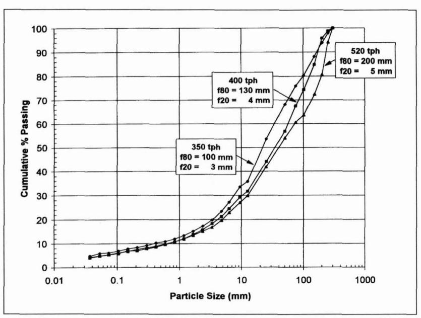
Comparing the typical feed size distributions allowing a milling rate of 400 and 520 tph, there is a 10% increase of the plus 100 mm component ie. source of grinding media. Comparing the typical feed size distributions allowing a milling rate of 400 and 350 tph, there is a 5% decrease of the plus 100 mm component. (The feed size distribution allowing 520 tph rarely occurs for extended periods of time.)
Feed sizings with a \( f_{80} \) (80 % passing size) of 130 mm and greater, but with an increase in the amount of "critical size" material (25 mm to 50 mm) have also resulted in lower milling rates.
During these periods, "crash stops" were performed and it was found that excessive amounts of the "critical sizen material were accumulating in the autogenous mills. This suggested that an increase in the amount of the "critical size" material in the mill feed also caused a decrease in throughput.
During 1992 and 1993 a study was performed to investigate the possibility of correlating the mill power draw with the feed size distribution and the rnilling rate in fully autogenous open circuit operation (Valery Jr., 1993). This work included up to 30 fully autogenous open circuit feed surveys and the following empirical relationship was obtained.
where:
W = mill power draw (MW), TPH = mill feed rate (tph), f,, = size (mm) at which 80% of the feed passes, f2, = size (mm) at which 20% of the feed passes, a = slope of the log-log particle size distribution of the feed and R2 is the regression coefficient.
This correlation has been used for predicting the effect of the feed size distribution on the fully autogenous open circuit milling rate. Feed sizings continue to be performed on a routine basis to increase the feed size data base and also to give a quantitative measure of feed size distribution variations. This information is also fed back to the mining department to help optimise mining practices.
Semiautogenous operation in open circuit - % ball charge
It has been shown that the fully autogenous open circuit milling rate is strongly influenced by the feed size distribution. It has also been mentioned that at times of fine feed, production targets are difficult to reach. To maintain production targets at times of fine feed, mill 2 is operated in the semi-autogenous open circuit mode. (Mill 1 remains in the fully autogenous open circuit mode.)
During a period of fine feed, semi-autogenous open circuit trials using 80 mm steel balls were performed to determine the percent ball charge required to maintain specific rnilling rate targets. Feed size distributions were also obtained throughout the trials. The results of the trials are shown in Figure 4.
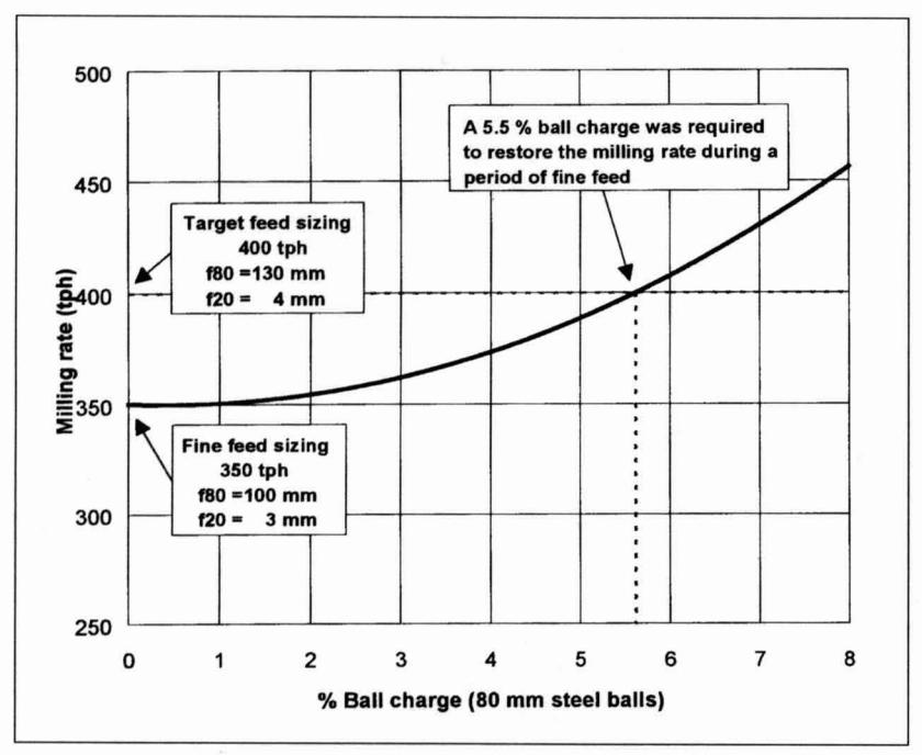
With a feed containing a \( f_{80} \) of 130 mm and a \( f_{20} \) (20% passing size) of 4 mm, the fully autogenous open circuit milling rate target of 400 tph can be maintained. During a period of fine feed ( \( f_{80} \) of 100 mm and a \( f_{20} \) of 3 mm), the milling rate decreased to 350 tph. Semi-autogenous open circuit trials performed during this time period showed that a ball charge of 5.5 % was required to restore the milling rate. One interesting observation was that a ball charge of 2% did not have a great effect on the milling rate.
After a change in mining practices, consequently coarsening the feed size distribution, mill 2 was changed to fully autogenous open circuit mode. In August 1995, a change in mining practices caused the feed size distribution to become fine. This required mill 2 to be operated again in the semi-autogenous open circuit mode. During this time period, test work was performed to determine if the 80 mm steel balls were in fact the optimum ball size to use in semi-autogenous open circuit milling.
Results from these tests showed that 100 mm steel balls would result in more efficient grinding in the semi-autogenous open circuit mode than the 80 mm steel balls. The 80 rnm steel balls have since been replaced by the 100 mm steel balls and are performing successfully.
Semi-autogenous operation in closed circuit - closing the circuit with hydrocyclones (full recycle)
Although the target milling rate of 400 tph was achieved in the semi-autogenous open circuit mode, this mode of operation is not the most efficient in terms of power utilisation. Running in the semi-autogenous closed circuit mode would improve the grinding efficiency of the mill in terms of power utilisation.
Semiautogenous closed circuit test work was performed in conjunction with the JKMRC, in which the ball charge of the semiautogenous mill was increased from 4% to 6% and then to 8% of the mill volume. The mill was in closed circuit with 690 mm inclined hydrocyclones. The data collected were analysed using the minerals processing simulator JKSIMMET, and simulations were produced to determine the maximum possible closed circuit milling rate at each ball charge. The results of the simulations are shown in Table 2.
The simulations showed that a maximum throughput of only 380 tph was possible by running the mill in the semi-autogenous closed circuit mode with an 8% ball charge.
|
simulation
I |
simulation
2 |
simulation
3 |
simulation
4 |
|
|---|---|---|---|---|
| Autogenous Mill | ||||
| Circuit (open or closed) | open | closed | closed | closed |
| Feed rate (tph) | 400 | 360 | 340 | 380 |
| Power (kW) | 6,300 | 5,600 | 5,730 | 5,750 |
| l~all load (%volume) |
4
1 |
4
1 |
6
1 |
8
1 |
A significant drop in the power draw was also observed which was similar to that experienced during the early stages of cornmissioning in fully autogenous closed circuit operation.
Again, this was related to an accumulation of slurry at the toe of the charge, caused by insufficient grate and/or pulp lifter capacity to efficiently remove slurry from the mill.
Any further increase in feed rate caused the mill to overload with a high charge. Due to the higher liner wear caused by the low mill pulp density in semi-autogenous operation when compared to fully autogenous operation, a ball charge greater than 8% was not tested. The issue of the low mill pulp density (mentioned later in this paper) was required to be resolved before any semiautogenous trials were to be attempted with a ball charge greater than 8%.
Semi-autogenous operation in closed circuit - partial recycle of cyclone underflow
Operating the mill in the semi-autogenous closed circuit mode is favoured over semi-autogenous open circuit operation because closed circuit operation improved the grinding efficiency in terms of power utilisation. However, the target throughput of 400 tph could not be achieved in closed circuit operation. Because of the preference of semi-autogenous closed circuit operation, it was decided to investigate the effect of the semi-autogenous cyclone underflow recycle on throughput, ie. partial recycle.
When a fully autogenous or semi-autogenous mill circuit is closed, the volumetric flow of slurry through the mill increases.
If the flow becomes excessive, an accumulation of slurry at the toe of the charge results, reducing the power draw and consequently causing deterioration in grinding performance (Morrell and Kojovic, 1996). However, if the slurry flowrate is not excessive, performance is not affected and as a result a finer circuit product sizing can be obtained without compromising throughput. Power utilisation is therefore enhanced. It was expected that, for the same grates and pulp lifter configuration, there would be a level of slurry recycle that could be accommodated by the mill to give the required throughput of 400 tph at a finer product sizing.
The line 2 semiautogenous grinding circuit had to be modified to include a cyclone underflow by-pass system allowing the recycle load to be controlled. Figure 5 shows the modified autogenous grinding circuit (Valery Jr. and Morrell, 1995).
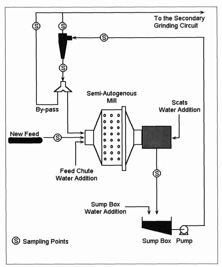
The ball charge of the semi-autogenous mill was increased from 4% to 6% and then to 8% and for each of these ball charges, the semi-autogenous cyclone underflow recycle was varied from 0% to 100%. A total of eight primary grinding surveys was performed.
The survey data was analysed using JKSIMMET, and simulations of the grinding circuit were produced to determine the effect of cyclone underflow recycle on the semi-autogenous mill performance. Simulations were performed at a 4% ball charge in fully open circuit, 50% closed circuit, 70% closed circuit and 100% closed circuit. The results of the simulations are shown in Table 3. To give a better description of the cyclone overflow size distribution, values of the cyclone overflow p, (50% passing size) are presented.
|
simulation
5 |
simulation
6 |
simulation
7 |
simulation
8 |
|
|---|---|---|---|---|
| Autogenous Mill | ||||
| Recycle (%) | 100 | 70 | 50 | 0 |
| New feed rate (tph) | 360 | 390 | 400 | 400 |
| Discharge flowrate (m³/hr) | 688.3 | 501.2 | 433.6 | 303.7 |
| Discharge % solids | 70.6 | 73.1 | 72.5 | 71 |
| Total mill load (% volume) | 30.4 | 27.1 | 26.5 | 27.1 |
| Product p 50 (micron) | <37 | 55 | 78 | 103 |
The simulations showed that it was possible to achieve a throughput of 400 tph and a cyclone overflow p, of 103 microns, by operating the mill in semi-autogenous open circuit mode (4% ball charge). However, semi-autogenous 50% partially closed circuit operation (4% ball charge) achieved a throughput of 400 tph and a cyclone overflow p,, of 78 microns. This was a substantial improvement in the grinding efficiency of the primary grinding circuit as was expected with the benefits of partial closed circuit operation.
Semi-autogenous operation in closed circuit - increasing the grate open area
From the previous trials of semi-autogenous closed circuit operation and semi-autogenous partial closed circuit operation, it was evident that a discharge limitation continued to exist.
However, it was unclear if the discharge limitation was caused by the grate discharge mechanism or by the pulp lifter discharge mechanism.
To alleviate the discharge limitation of the mill, the grate open area needed to be increased and/or the pulp lifter capacity needed to be increased. Since it was easier to modify the grate open area than to modify the pulp lifter design, it was decided to increase the grate open area on both autogenous mills.
Simulations of increasing the grate open area were conducted. The results showed that a throughput of 420 tph could be obtained with a 33% increase in grate open area at an 8% ball charge. An assumption here is that the grate discharge capacity is lower than the pulp lifter discharge capacity.
Semi-autogenous operation in closed circuit - increasing the mill pulp density.
Water is added to an autogenous mill in three ways, the moisture in the feed which is negligible, the water added to the feed end of the mill and the water added in the form of the scats return system (A high pressure water jet installed at the trommel to transport the scats back into the mill).
Mill liner wear was high in semi-autogenous operation when compared to fully autogenous operation. This was due to the low mill pulp density caused by the high water flowrate of the scats return system which was required to transport the scats back in to the mill. The water flowrate of the scats return system is, to a certain extent, determined by the aperture of the grates. If the scats water addition is decreased with the current grate aperture, the scats return system runs a high risk of blocking which results in the mill having to be shut down. A method was required to increase the mill pulp density without affecting the scats return system.
It was decided to decrease the grate aperture from 20 mm to 12 mm while maintaining the 33% increase in grate open area. With a smaller grate aperture, the size of the scats reporting to the trommel should decrease, allowing the water flowrate of the scats return system to be reduced. This should result in an overall increase in the mill pulp density. To assist in maintaining a consistently high mill pulp density (70% \( \sim \) 72% solids by weight), a density controller has been installed which sets the feed chute water addition by ratio from the mill feed rate.
In the past each autogenous mill was operated at fixed feed chute water addition, allowing the mill pulp density to vary with varying feed rate.
The wear of the mill shell lining was expected to decrease in semi-autogenous operation with an increase in the mill pulp density. These new grates are currently being tested in semiautogenous operation and initial results have shown improved liner wear.
REMOVAL OF ONE BALL MILL FROM THE SECONDARY GRINDING CIRCUIT
With the knowledge gained from these trials and trials performed in the secondary grinding circuit, models of the grinding circuit have been produced using JKSIMMET. Simulations were performed to determine the possibility of removing one ball mill from the secondary grinding circuit with the autogenous mills in their most efficient modes of operation.
During the simulations, it was found that the autogenous mills, milling at 400 tph in semi-autogenous mode (4% ball charge) and 50% partial closed circuit, were operating close to full capacity. In order to obtain extra capacity and to avoid operational problems, coarse classifiers such as DSM screens were used to replace the hydrocyclones in the primary grinding circuit.
The use of DSM screens has the advantage of resulting in a better classification for the required coarse cut size, reducing the problem related to the power limitation which is caused by the build up of slurry in the autogenous mills in closed circuit operation. However, DSM screens would require a high capital investment including a significant modification to the current autogenous mill trommel design and primary grinding circuit layout. Therefore, the alternative of partially closing the autogenous mills with hydrocyclones was considered for the initial plant trials.
Different combinations of hydrocyclones and operating conditions in both the primary and secondary grinding circuits were investigated. Various combinations of spigot and vortex finder diameters and cyclone feed pressures were also investigated. The simulations showed that it was possible to remove one ball mill from the secondary grinding circuit which produced a flotation feed which was slightly coarser than for the original crushinglgrinding circuit.
The grinding circuit chosen for the initial full plant trial to remove a ball mill from the secondary grinding circuit has mill 1 in the fully autogenous open circuit mode and mill 2 in the semi-autogenous partial closed circuit mode. The product from this primary grinding circuit will report to a cluster of three 660 mm vertical scalping hydrocyclones. The underflow from the scalping cyclones will combine with the remaining secondary ball mill discharge. The secondary ball mill will be in closed circuit with four 660 mm vertical hydrocyclones. The cyclone overflow from the secondary grinding circuit will combine with the scalping cyclone overflow to produce the flotation feed. Simulations of this circuit produced a flotation feed with a p,, of 170 microns.
Full scale test work has been planned for August 1996 with the aim of eliminating the use of one ball mill in the secondary grinding circuit at the current production target of 6.0 Mtpa.
CONCLUSIONS
In the copper concentrator, a traditional crushing and primary grinding circuit was replaced by two autogenous grinding mills in June 1991. The resulting flotation feed size was reduced from a p,, of 150 microns to 100 microns. Liberation and flotation studies showed no significant benefits of a finer flotation feed.
Test work was conducted by MIM in conjunction with the JKMRC to study circuit alternatives and the effect of operating variables to achieve maximum performance of the autogenous mills. The results of this test work are summarised.
With the knowledge gained from these trials, and trials performed in the secondary grinding circuit, models of the complete grinding circuit have been produced using JKSIMMET. Simulations of the complete grinding circuit, with the autogenous mills in their most efficient modes of operation, have shown that it is possible to remove one ball mill from the secondary grinding circuit. This will produce a flotation feed with a p,,of 170 microns which is slightly coarser than the product sizing for the original crushinglgrinding circuit (p, of 150 microns) at the current production target of 6.0 Mtpa.
Full scale test work has been planned for August 1996 with the aim of eliminating the use of one ball mill in the secondary grinding circuit at the current production target of 6.0 Mtpa.
ACKNOWLEDGMENTS
The authors would like to acknowledge the assistance of all the personnel responsible at Mount Isa Mines Limited for the execution of all the autogenous and semi-autogenous trials performed at the copper concentrator. The authors would also like to acknowledge the staff at the JKMRC for their assistance in this paper and for work conducted on site at the copper concentrator. Finally, the authors would like to thank the management at Mount Isa Mines Limited for the permission to publish the data.
REFERENCES
Leung, K., Lumsdaine, I., Veran, V. P., 1992 "Decision of Mount Isa Mines Limited to change to autogenous grinding". Comminution Theory and Practice , K.Kawatra (ed.) pp 331-338.
Griffin, L. K., Hart, S., Espinosa-Gomez, R., Johnson, N. W., 1993 "Chalcopyrite Flotation and Liberation Characteristics Before and After Autogenous Grinding at Mount Isa Mines Limited". XVIII International Mineral Processing Congress, May 23-28, Sydney, Australia, Vol 4, pp 913-922.
Valery Jr., W., 1993 "Investigation of the Dynamic Behaviour of the MIM Copper Concentrator Autogenous Mills", JKMRC/AMIRA P9K project report, Brisbane, Australia.
Valery Jr., W. and Morrell, S., 1995 "The development of a dynamic model for autogenous and semi-autogenous grinding". Minerals Engineering Conference ' 95, St. Ives, England, Vol. 8, No.11, pp 1285-1297.
Morrell, S. and Kojovic. T., 1996 "The influence of slurry transport on the power draw of autogenous and semi-autogenous mills". SAG Conference 1996, October 6-9, Vancouver, B.C., Canada.
APPENDIX 1
Copper Concentrator Autogenous mills:
| Manufacturer: Boliden-Allis Chalm | iers |
|---|---|
| Diameter inside shell: | 5 m |
| Diameter inside liners : | |
| Belly length inside liners: 5.29 | m |
| Mill cylinder length: 4.4 |
APPENDIX 1(cont'd)
| Centre line length: | |
|---|---|
| m | |
| Mill volume: | 375 m³ |
| Grate aperture: | . 32 grates with 17 slots of 12 mm |
| Fraction of grate open area: | 5.4% |
| Trommel aperture : | |
| Ball charge (% mill volume): | varied from 0 to 8% |
| Ball top size : | 100 mm |
| Mill speed: | fixed 10.7 r.p.m. (76.5% critical) |
| Autogenous Mill Hydrocyclones: | |
| (2 clusters of 2 inclined cyclones, all operating) | |
| Manufacturer: | Linatex |
| Diameter: | 0.675 m |
| Length of cylindrical section : | 0.356 m |
| Inlet diameter: | 0.203 m |
| Spigot diameter : | 0.165 m |
| Vortex finder diameter : | 0.290 m |
| Cone angle: | 20 degrees |
| Copper Concentrator Ball mills: | |
| 2 operating | |
| Manufacturer: | Allis Chalmers |
| Manufacturer: Diameter inside shell: | |
| 5.03 m | |
| Diameter inside shell: | 5.03 m |
| Diameter inside shell: Diameter inside liners: Belly length inside liners: Centre line length: | |
| Diameter inside shell: Diameter inside liners: Belly length inside liners: Centre line length: Speed: | |
| Diameter inside shell: Diameter inside liners: Belly length inside liners: Centre line length: Speed: % critical speed: | 5.03 m 4.85 m 5.92 m 6.10 m 14 r.p.m 72.8 |
| Diameter inside shell: Diameter inside liners: Belly length inside liners: Centre line length: Speed: % critical speed: Ball top size: | 5.03 m 4.85 m 5.92 m 6.10 m 14 r.p.m 72.8 65 mm |
| Diameter inside shell: Diameter inside liners: Belly length inside liners: Centre line length: Speed: % critical speed: | 5.03 m 4.85 m 5.92 m 6.10 m 14 r.p.m 72.8 65 mm |
| Diameter inside shell: Diameter inside liners: Belly length inside liners: Centre line length: Speed: % critical speed: Ball top size: | 5.03 m 4.85 m 5.92 m 6.10 m 14 r.p.m 72.8 65 mm 2610 kW |
| Diameter inside shell: Diameter inside liners: Belly length inside liners: Centre line length: Speed: % critical speed: Ball top size: Rated power: Ball load fraction: Ball Mill Hydrocyclones: | 5.03 m 4.85 m 5.92 m 6.10 m 14 r.p.m 72.8 65 mm 2610 kW |
| Diameter inside shell: Diameter inside liners: Belly length inside liners: Centre line length: Speed: % critical speed: Ball top size: Rated power: Ball load fraction: | 5.03 m 4.85 m 5.92 m 6.10 m 14 r.p.m 72.8 65 mm 2610 kW |
| Diameter inside shell: Diameter inside liners: Belly length inside liners: Centre line length: Speed: % critical speed: Ball top size: Rated power: Ball load fraction: Ball Mill Hydrocyclones: | |
| Diameter inside shell: Diameter inside liners: Belly length inside liners: Centre line length: Speed: % critical speed: Ball top size: Rated power: Ball load fraction: Ball Mill Hydrocyclones: (2 clusters of 6 cyclones, 5 or 6 operating per cl Manufacturer: Diameter: | 5.03 m 4.85 m 5.92 m 6.10 m 14 r.p.m 72.8 65 mm 2610 kW 0.41 \nuster) Krebs (D20B) 0.508 m |
| Diameter inside shell: Diameter inside liners: Belly length inside liners: Centre line length: Speed: % critical speed: Ball top size: Rated power: Ball load fraction: Ball Mill Hydrocyclones: (2 clusters of 6 cyclones, 5 or 6 operating per cl | 5.03 m 4.85 m 5.92 m 6.10 m 14 r.p.m 72.8 65 mm 2610 kW 0.41 \nuster) Krebs (D20B) 0.508 m |
| Diameter inside shell: Diameter inside liners: Belly length inside liners: Centre line length: Speed: % critical speed: Ball top size: Rated power: Ball load fraction: Ball Mill Hydrocyclones: (2 clusters of 6 cyclones, 5 or 6 operating per cl Manufacturer: Diameter: Length of cylindrical section: Inlet diameter: | 5.03 m 4.85 m 5.92 m 6.10 m 72.8 65 mm 2610 kW 0.41 \nuster) Krebs (D20B) 0.508 m 0.770 m 0.118 m |
| Diameter inside shell: Diameter inside liners: Belly length inside liners: Centre line length: Speed: % critical speed: Ball top size: Rated power: Ball load fraction: Ball Mill Hydrocyclones: (2 clusters of 6 cyclones, 5 or 6 operating per cl Manufacturer: Diameter: Length of cylindrical section: Inlet diameter: Spigot diameter: | 5.03 m 4.85 m 5.92 m 6.10 m 72.8 655 mm 2610 kW 0.41 \nuster) Krebs (D20B) 0.508 m 0.770 m 0.118 m 0.108 m |
| Diameter inside shell: Diameter inside liners: Belly length inside liners: Centre line length: Speed: % critical speed: Ball top size: Rated power: Ball load fraction: Ball Mill Hydrocyclones: (2 clusters of 6 cyclones, 5 or 6 operating per cl Manufacturer: Diameter: Length of cylindrical section: Inlet diameter: Spigot diameter: Vortex finder diameter: | |
| Diameter inside shell: Diameter inside liners: Belly length inside liners: Centre line length: Speed: % critical speed: Ball top size: Rated power: Ball load fraction: Ball Mill Hydrocyclones: (2 clusters of 6 cyclones, 5 or 6 operating per cl Manufacturer: Diameter: Length of cylindrical section: Inlet diameter: Spigot diameter: |