



The content on this page was automatically generated from the PDF publication document and may contain errors or inaccuracies. Please refer to the original PDF for the most accurate information.
INFLUENCE OF DISCHARGE PULP LIFTER DESIGN ON SLURRY FLOW IN MILLS
Sanjeeva R Latchireddi and Stephen Morrell Julius Kruttschinitt Mineral Research Centre University of Queensland Australia
ABSTRACT
The difficulties associated with slurry transportation in autogenous (ag) and semi-autogenous (sag) grinding mills have become more apparent in recent years with the increasing trend to treat large tonnages. This is particularly noticeable when ag/sag mills are run in closed circuit with classifiers such as fine screens/cyclones. To understand the performance characteristics of grates/pulp lifters and to produce an appropriate tool for mill designers, a research program was initiated at the Julius Kruttschnitt Mineral Research Centre (JKMRC).
Experiments were carried out in pilot scale mill where the influence of both design and size of the discharge pulp lifters as well as other important variables were studied. Ideally, the pulp lifters should transport all the slurry, which is passing through the discharge grate, into the discharge trunnion. However, the results obtained have clearly shown that this may not be the case, and that pulp lifters with insufficient volume will provide severely limited flow capacity. The main factor that contributes to this poor performance is flow-back of slurry from the pulp lifter into the mill.
Out of the understanding of conventional pulp lifters a new design of pulp lifter called the 'Twin Chamber Pulp Lifter (TCPL)' has been developed to overcome the problem of flow-back. The TCPL has been thoroughly tested at the pilot scale and the results have shown that it largely eliminates flow-back. This performance has been confirmed at the industrial scale trial in 7.7m sag mill at Alcoa World Alumina Australia's Wagerup Refinery which increased the throughput over 15 percent.
RESUME
Sanjeeva R.Latchireddi: Sanjeeva Latchireddi obtained the degree of M.Tech. in 1989 from Indian School of Mines in Minerals Engineering. From 1989-1990 he worked for Indian Rare Earths Ltd. in modifying the process flowsheet. In 1990 he joined Regional Research Laboratory (CSIR-India) as a research scientist where he worked on processing of coal and minerals and successfully completed a number of industry sponsored projects. During 1992-93, he visited Poland under Indo-Polish young scientists exchange program. On winning the AUSAID fellowship in 1995, he joined JKMRC as a Ph.D research scholar to work in the field of slurry transportation in ag/sag mills. He has invented a new design of discharge pulp lifters and got over 15 publications to his credit. He is currently preparing his thesis.
Dr Stephen Morrell: Steve Morrell graduated in 1980 from the Royal School of Mines with the degree of B.Sc. (Eng.) in metallurgy. From 1980 to 1987 he worked for De Beers in Namibia and Botswana in production, research and development, plant design and commissioning. In 1987 he joined the JKMRC as a research scholar and obtained the degree of M.Eng. in 1989 in the field of semi-autogenous milling. He subsequently joined the staff of the Research Centre and continued part time study which lead to his receiving in 1993 a PhD in the prediction of mill power. In 1994 he was awarded the Zinc Corporation prize for his PhD. This was subsequently followed by the Wardell-Armstrong prize in 1996 for 2 papers he published on his PhD work. He is currently Manager - Comminution Research, responsible for the direction of the Centre's comminution research.
INTRODUCTION
Autogenous (ag) and semi-autogenous (sag) grinding mills have been in use in the mining industry since the early part of this century (Robinson 1980) and now dominate comminution circuit design. The progressive introduction of ag/sag mills has been accompanied by a steady increase in mill size and unit throughput. As a result mill diameters now reach 12.2m, power draw is as high as 20 MW and throughputs may exceed 3000 tph per machine. This trend and the increasing popularity of single, high throughput grinding lines when coupled with a move towards close circuiting ag/sag mills has focused attention on the ability of the grate/pulp lifter assembly to efficiently remove high volumes of slurry. A schematic of a typical AG/SAG mill and its discharge assembly is shown in Figure 1.
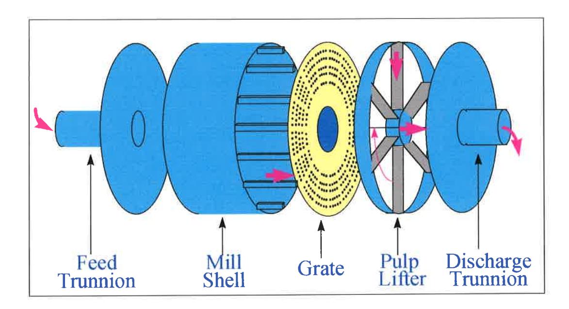
Ore and water are fed into the mill. Once the ore is broken to below the size of the grate holes, the ground ore particles and water flow through the grate as a slurry and into the pulp lifters. This is the first stage of the slurry discharge process. The second stage involves the transportation of slurry from the pulp lifters into the discharge trunnion.
In the past little or no work has been reported on how the grate/pulp lifter assembly functions and in particular what is the influence of pulp lifter design. The literature does contain some references to pulp lifter design, the most noticeable being Mokken et al (1975) who listed some of the disadvantages due to poor pulp lifter performance. In addition, Rowland and Kjos (1975) stated that the load carrying capacity of pulp lifters is perhaps more important than the grate open area for a successful mill operation. This was reiterated by both Bond and Kjos (1985).
Due to the lack of published information and industrial experience at some sites which strongly indicated the importance of slurry transport (Morrell and Kjovic, 1996), a project was initiated at the JKMRC to study the influence of grate and pulp lifters on the flow capacity of mills.
EXPERIMENTAL
An extensive test work program was carried out using lab and pilot scale mills with diameters of 0.3 and 1 meter respectively. A schematic diagram of the pilot mill and ancillaries is shown in Figure 2. The feed tank consisted of three sections divided by two wear plates. The pump output flowed into the first section and overflowed into the middle section. Overflow from the middle section was fed back to the sump through the third section. This arrangement ensured a constant pressure head in the middle section whose discharge flowed into the mill through two knife gate valves - one just below the feed tank to vary the feed flowrate, and the other near the feed trunnion to stop the flow into the mill when required.
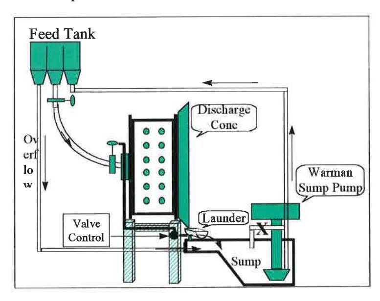
The mill discharge flowed into a sump through a movable launder below the discharge cone. When in operation water was pumped to the steady-head feed tank from where it gravitated into the mill. The mill was run at a variety of speeds with a range of media fillings. Media composed 25 mm steel balls. Different grate/pulp lifter designs at different flow rates into the mill was tested. Each test comprised allowing the mill to equilibrate then crash stopping the mill and measuring the volumetric hold-up of water in the mill. To do so the knife valve near the feed trunnion was shut off and at the same time the mill was stopped and a hydraulic cram diverted the discharge launder so that it discharged into a sampling drum. The remaining water in the charge was then drained off into the same drum via a valve in the mill shell.
ASSESSING THE PERFORMANCE OF CONVENTIONAL PULP LIFTER DESIGNS
The width of the pulp lifter determines its capacity and hence the pulp lifter size was represented as the percent ratio of the pulp lifter width to the mill length [Percent ratio = (Pulp lifter width / mill length)*100] as given below
| Pulp lifter size | Percent ratio |
|---|---|
| Small | 3.7 |
| Medium | 6.8 |
| Large | 9.9 |
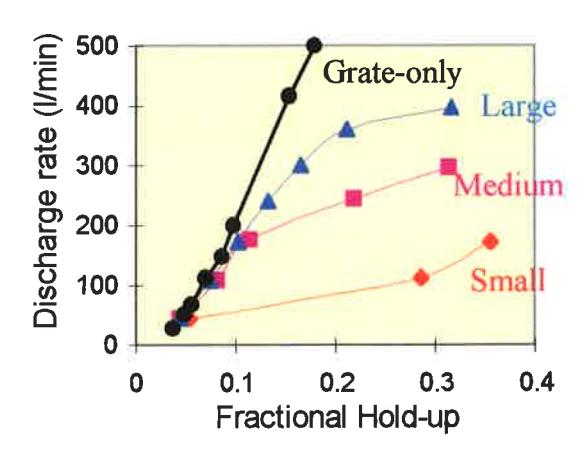
For a given hodup the maximum flow that can occur is that coming out of the grate where no pulp lifter is attached. If the pulp lifters have sufficient capacity, the discharge rate of a grate/pulp lifter discharge assembly would be equal to the discharge rate through the grate-only system. If not, it will deviate from the grate-only discharge flow rate. The degree of deviation from the grate-only performance therefore indicates the inefficiency of the pulp lifter.
Based on this concept, the performance of different designs of pulp lifter were analysed. It was found from the test results that conventional pulp lifters were considerably less efficient over a wide range of pulp lifter sizes. This can be seen clearly in Figure 3 in terms of the difference between the ideal (grate-only discharge) and the different pulp lifter plots.
The inefficiency of conventional designs of pulp lifters may be attributed to flow-back and carry-over processes as described by Latchireddi and Morrell (1997a). Both these processes can be explained using Figure 4, where the fluid profiles both inside the mill as well as in each section of pulp lifter assembly are shown.
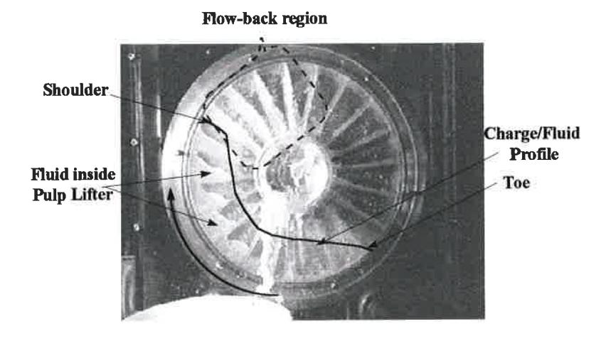
As can be seen from Figure 4 the flow from the pulp lifter into the discharge trunnion starts around the shoulder position of the charge where the gravitational force exceeds the centrifugal force. However, above the shoulder, there will not be any grinding media inside the mill sitting against the face of the grate. Hence the slurry inside the pulp lifter flows back into the mill until it is discharged completely. If the slurry inside the pulp lifter is not discharged completely, it is carried-over to the next cycle. This, however, is only expected to occur at high mill speeds.
DEVELOPMENT OF A NEW DESIGN OF PULP LIFTER
The best way to overcome the inefficiencies of the conventional designs is to ensure no flow-back of slurry occurs once the slurry has entered the pulp lifter. This has been achieved by developing a new design of pulp lifter called the Twin Chamber Pulp Lifter (TCPL) (Latchireddi and Morrell, 1997b) a schematic of which is shown in Figure 5.
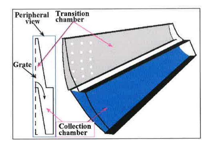
Slurry enters the section exposed to the grate - called the transition chamber, and then flows into the lower section - called the collection chamber which is not exposed to the grate. This mechanism ensures that the slurry is unable to flow or drain backwards into the mill, and hence the flow-back process is prevented up to the capacity of the collection chamber. This can be precisely designed to handle the desired discharge flow rate through the mill.
Performance comparison of different pulp lifter designs
A pilot mill size TCPL assembly was made equal in size of radial and curved pulp lifters, and was tested under different operating conditions. To compare the performance, the mill hold-up and discharge rate relations, at the same operating condition, were plotted for all the pulp lifter designs as shown in Figure 6.
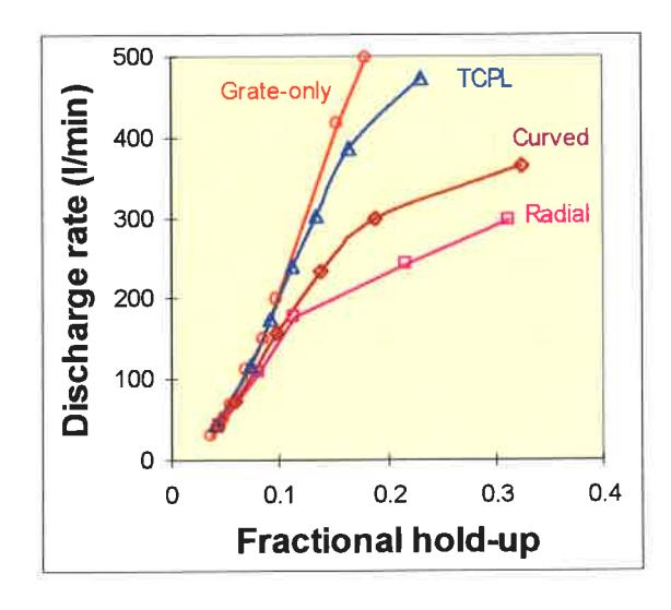
As expected the performance of the TCPL is close to the ideal or grate-only line over most of the flow rate range. This is significantly better than both radial and curved designs. It is apparent from these data that for the same slurry hold-up, the mill can be operated at a higher flow capacity by using TCPL compared to the conventional pulp lifter designs.
Influence of open area and charge volume on performance of the RPL
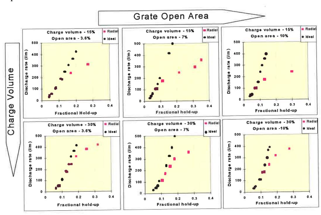
Grate open area: It is usual practice to increase the open area of the slots or holes in a grate to attempt to obtain an increased discharge rate. This may be successful with grate-only discharge mechanisms. However, in the case of grate-pulp lifter discharge assemblies which are pulp lifter limited, the effective discharge rate out of the mill may be reduced by allowing more slurry to flow back into the mill. This is illustrated in Figure 7 by the increasing difference between the grate-only and grate-pulp lifter lines as open area is increased. This is in accordance with the statement made by Rowland and Kjos (1975) that if the pulp lifters do not have enough capacity, the typical approach of increasing the grate area does not improve the situation, but makes it worse by allowing the slurry to flow back into the mill. However, the magnitude of this difference reduces with increasing charge volume.
Charge volume: As illustrated in Figure 4, the cross-sectional area of grate covered by the charge helps in reducing flow-back. This can be seen in Figure 7 in the decreasing magnitude of the difference between the grate-only and grate-pulp lifter flow lines as the charge volume increases from 15 to 30 percent. This trend is apparent for all grate open areas tested. These observations suggest that the performance of conventional radial pulp lifters is highly dependent on the interaction between grate open area and charge volume. The later being a strong function of the competence of the ore fed to the mill in the case of ag and sag mills.
Influence of open area and charge volume on performance of the TCPL
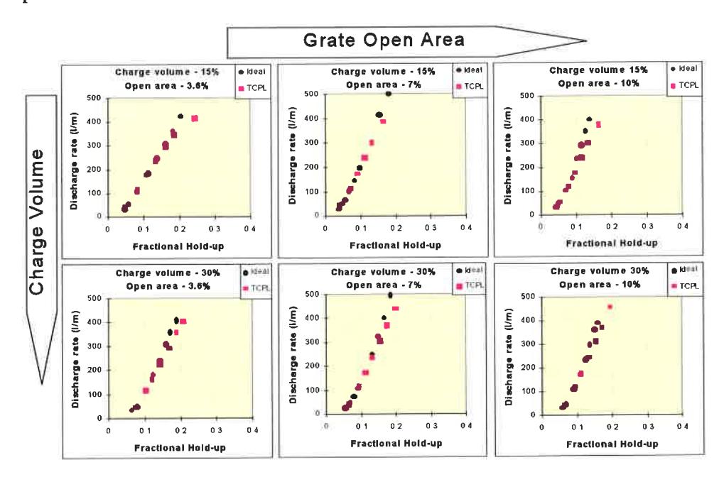
Contrary to the observations made in Figure 7, it can be seen from Figure 8 that the performance of the TCPL is not influenced in the same manner as the RPL as over most of the flow rate range it is not rate limiting. This is clearly seen up to the discharge capacity of the collection chamber. This is because once the slurry flows into the collection chamber it is not exposed to the grate holes. However, beyond the capacity of the collection chamber both charge volume and open area have a similar effect as that of RPL.
INDUSTRIAL TRIALS OF TWIN CHAMBER PULP LIFTER (TCPL)
The clear ability of the TCPL to achieve a higher discharge flow rate, closer to the maximum flow capacity of the mill, for a given hold-up prompted Alcoa World Alumina Australia to trial this design in one of its 7.7 m diameter sag mills at its Wagerup Refinery in Western Australia. The sag mill operates in closed circuit with DSM screens whose final grind size is around 65 percent passing 150 microns. The circuit receives –250 mm crushed bauxite ore and is treated in the presence of caustic soda with a milling circuit temperature around 95 deg.C. This is the first full scale industrial trial of the TCPL whose installation and commissioning was carried out in August 1999.
To assess the effect of the TCPL over the existing RPL, a complete survey around the sag mill circuit was conducted both before and after the installation. For the survey prior to installation the mill was running at its maximum capacity, at which point slurry just starts to overflow out of the feed end of the mill. This was followed by running the mill at different throughputs to estimate the maximum capacity that could be achieved under the prevailing operating conditions. All the surveys were followed by a crash stop of the mill to measure the instantaneous charge and slurry volumes. The slurry hold-up values at different feed tonnage going through the mill for both pre and post installation of the TCPL are shown in Figure 9. The ideal slurry hold-ups required to fill the voids of media without any slurry pooling are also shown for comparison.
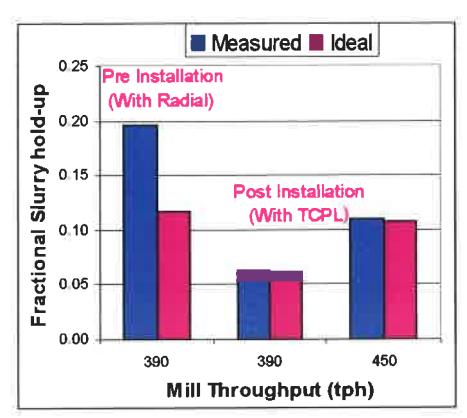
It can be seen that at the pre-TCPL installation the maximum throughput was 390 tph and the slurry hold-up was almost 20% by volume. When the mill was crash stopped a slurry pool of more than 0.7 meters deep was measured above the charge level. After installation of the TCPL the hold-up reduced to 6% and the slurry pool disappeared. This resulted in a higher throughput being achieved which increased from 390 to 450 tph. Despite the 15% increase in mill throughput, the product size distribution has remained unaffected.
CONCLUSIONS
The discharge pulp lifters should be designed to handle the discharge flow rate for a successful mill operation. The design of the Twin Chamber Pulp Lifter (TCPL), volume-for-volume, offers the most efficient performance when compared to conventional designs.
- the TCPL design stops flow-back from occurring
- the TCPL allows the mill to operate as close as possible to its maximum flow capacity with out slurry pooling.
- with TCPL, the dependency of the pulp lifter's performance on the interaction between grate design and the volume of grinding media inside the mill can be eliminated.
- the TCPL can be precisely designed to handle the required flow capacity during the design stage
The industrial trials of TCPL in 7.7 meter sag mill at Wagerup operations of ALCOA has proved the ability of TCPL in ensuring the best grinding environment inside the mill through efficient slurry transportation. This resulted in increasing the mill throughput by over 15%.
ACKNOWLEDGEMENTS
The authors are grateful to ALCOA for conducting the first full scale trials of TCPL and permitting to publish the results, ANI Mineral Processing for providing the pilot scale mill and CSIRO for the flow visualisation studies. The scholarship provided by AUSAID and the sponsors of the AMIRA P9L project at JKMRC are gratefully acknowledged.
REFERENCES
1. Bond, F. C., 1985. History of autogenous grinding. SME Mineral Processing Handbook N.L.Weiss (Ed) Vol.1, SME, New York, pp. 3c-57 - 3c-60
- 2. Kjos, D. M., 1985. Wet autogenous mills. SME Mineral Processing Handbook N.L.Weiss (Ed) Vol.1, SME, New York, pp. 3c-60 3c-75
- 3. Latchireddi, S. R. and Morrell, S., 1997a. A laboratory study of the performance characteristics of mill pulp lifters. Minerals Engineering, Vol.10, No.11, pp. 1233-1244.
- 4. Latchireddi; S. R. and Morrell, S., 1997b. International Patent Application No. PCT/AU97/00418, Twin Chamber Pulp Lifters for Grate Discharge Mills.
- 5. Mokken, A. H., Blendulf, G. K. I. and Young, G. J. C., 1975. A study of the arrangements for pulp discharge on pebble mills, and their influence on mill performance. J.South African IMM, May, pp.257-289
- 6. Morrell, S. and Kojovic, T., 1996. The influence of slurry transport on the power draw of autogenous & semi-autogenous mills. Proceedings of Int. Conf. Autogenous and Semi-autogenous Grinding Technology, Vancouver, B.C., pp. 378-389
- 7. Robinson, B., 1980. The history of autogenous grinding. CIM Bulletin, 73, pp. 114-118
- 8. Rowland, C. A. and Kjos, J. M., 1975. Autogenous and semi-autogenous mill selection and design. Australian Mining, September, pp. 21-35