



The content on this page was automatically generated from the PDF publication document and may contain errors or inaccuracies. Please refer to the original PDF for the most accurate information.
POWER MODELLING OF STIRRED MILLS
Aleksandar Jankovic and Stephen Morrell Julius Kruttschnitt Mineral Research Centre, Isles Rd, Indooroopilly 4068, Australia
ABSTRACT
Grinding of metaliferous ores is the energy intensive process demanding more than half of the energy consumed by conventional mineral processing plants. Minimizing the cost associated with grinding can therefore produce significant financial rewards. Understanding and quantifying the mechanisms affecting power draw of grinding mills and modelling, is a necessary step in that direction. Power models are also essential for equipment scale up and plant design purposes and may be directly incorporated into size reduction models for a complete description of the grinding process.
In this paper mathematical modelling of the power draw of stirred mills will be presented. The development of the power model, starting from simple empirical to the detailed mechanistic models will be explained and performance of the models will be compared. Application of the mechanistic models to the modelling of the size reduction grinding process will also be discussed.
INTRODUCTION
Power consumption is one of the main parameters which must be considered in determining the design and operational conditions for any mill. Power modelling of the tumbling mills is a well known subject in the comminution area and considerable knowledge about power consumption mechanisms has been collected during the many years of research. In contrast, there is little published information available regarding power correlation specifically for stirred mills. The subject has much in common with liquid mixing and attempts has been made to use this similarity for stirred mills power modelling (3, 4, 10, 11). This approach had a lot of deficiencies and it could be applied only for high speed mills (> 1000 rpm) with small diameter (< 3 mm) low density media.
The mechanistic approach, which assumes that power in stirred mills is consumed to overcome frictional resistance inside the mill has also been used. Based on a simplified model for the forces acting on the bottom and wall of the vessel, it was possible to derive an equation relating power requirements to the mill dimensions, velocity of pin tip and to the amount and nature of the charge (9). Model constants were determined by non-linear regression, but did not have physical meaning and can not be used for the onditions other than those tested. This raises the question about the model assumptions which do not seem to be valid because most of the friction is occurring between the grinding media. Another approach stated that the energy consumed by the mill is mainly due to friction between the balls which was determined by the pressure from the load over the balls (2). It was claimed that this model fitted experimental data well. Unfortunately the power equation was not published.
In a mill, particle breakage occurs at the contact point between two grinding media which are in motion. The frequency and energy of the media contacts are directly dependent on the mill design and media size, which are also controlling the mill power demand. Knowledge about the media motion is therefore necessary for the breakage modelling as well as for power draw modelling. Development of a mechanistic power draw model for vertical stirred mills, based on the media motion properties inside the mill will be presented in this work, as well as different levels of empirical modelling and their limitations.
TESTWORK
The equipment tested comprised a pilot Sala mill, pilot tower mill and laboratory scale (lab) pin, cylinder and tower mill. Results from several surveys of industrial tower mills were also available. The range of mills tested are presented in Table 1 and Figure 1. As can be seen, tower mill data covers a wide range of mill sizes, pin type mill data are limited to laboratory and pilot scale, whilst mills with a cylindrical type stirrer were tested only at laboratory scale.
| Table I - Des | scription | of the | Mills | Tested |
|---|---|---|---|---|
| Mill Type | Tower Mill | Sala Pin Mill | Cylinder Mill | |
|---|---|---|---|---|
| Orientation | Vertical | Vertical | Vertical | |
| Size description | lab, pilot, industrial | lab, pilot | lab | |
| Motor rated power (kW) | 0.25 - 1500 | 0.25 - 7.5 | 0.25 | |
| Stirrer design | Double helical steel screw | steel pins | cylinder with axial bars | |
| Stirrer speed (rpm) | 29 - 100 | 100 or 390 | 29 - 115 | |
| Chamber diameter (m) | 0.11 - 2.5 | 0.11 - 0.28 | 0.11 | |
| Media diameter (mm) | 2 - 20 | 2 - 8 | 2 - 6 | |
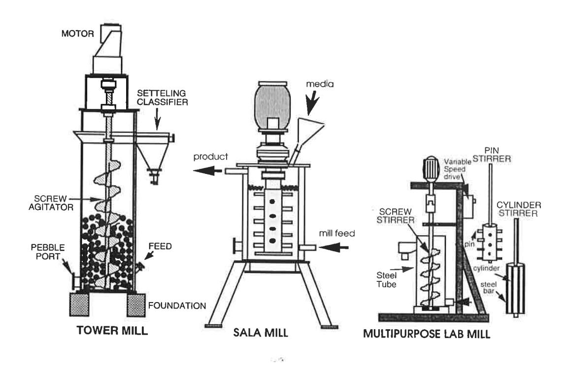
Mills were tested under different operating conditions and motor power draw was recorded through the test using a tong type power meter. Net mill power was calculated as the difference between mill power under the load and no load power. This accounts for the fraction of power used to move the grinding media inside the mill.
TESTWORK RESULTS
An extensive testwork program was carried out in order to provide data for modelling purposes and to study the mill power draw under different operating conditions. It was found during the test work that ariables affecting mill power draw were:
Major variables:
- mill size (diameter)
- mill type (stirrer design)
- stirrer speed
- amount of media (media height)
- media density
Variables of secondary importance:
- media size
- media size distribution
- media shape
- nature of the ground material
- size of the material being ground
- slurry density
The effect of the variables on stirred mill power draw is discussed in the following sections.
Mill Diameter
Mill diameter represents the size of the mill. As the mill vessels have a cylindrical shape, mill volume is a function of diameter squared. From basic principles, under constant media speed, mill power will be proportional to the volume of the media i.e. mill diameter squared. However, media speed at constant stirrer angular velocity is proportional to the mill diameter. It was reported that, in a pin type vertical stirred mill, power is proportional to the mill diameter cubed (9), and in the tower mill, proportional to the stirrer diameter to the power 3.057 (1).
Stirrer Speed
By increasing the stirrer speed, media velocity inside the mill increases. Power measurements at different stirrer speeds were carried out and results are presented in Figure 2. A linear trend can be observed for the all three stirrers design in the range of speed tested.
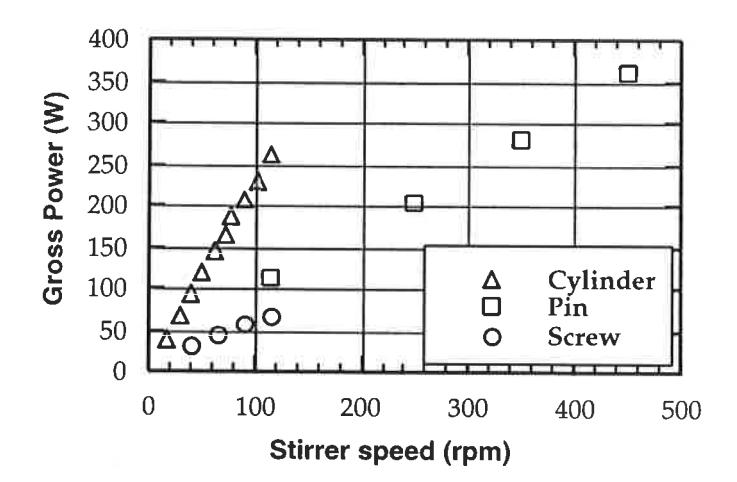
It can be concluded that irrespective from stirrer design, power draw is proportional to the stirrer speed.
Stirrer Design
Mill power draw is strongly related to the shape of the stirrer. In this study, three very different designs are tested: helical screw (tower mill), pin stirrer (Sala mill) and cylinder stirrer with a shaped surface. Outer stirrer diameters were the same. Using the same vessel, stirrer speed (115 rpm), media size (6 mm steel balls) and media volume, following net power draws were obtained:
It is obvious that power transfer to the media was very different indicating different force and media velocity distribution with different stirrers.
Slurry Properties
Experimental results indicated that the "buoyancy" force has an effect on the density of the mill charge (9). The effective density of the mill charge decreases with the slurry solids concentration and consequently so does the power draw.
where: \( \rho_{eff} \) = charge effective density (t/m3)
\( \varepsilon \) = charge void fraction \( \rho_{media} \) = media density (t/m3) \( \rho_{slurry} \) = slurry density (t/m3)
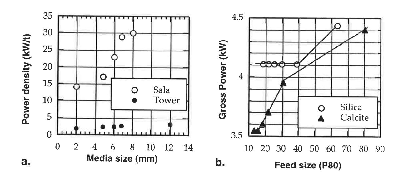
The size of the material being ground also affects the mill power draw, as can be seen from the Figure 4 b, showing the results from the pilot tests in the Sala pin mill at 100 kg, 6 mm balls load. Power draw decreasing with decreasing particle size for both calcite and quartz. Particle size decrease changes the slurry frictional properties and rheology. From a mechanical stand point, as material becomes finer, the friction coefficient is decreasing and so, therefore does the power draw. Slurry viscosity increases when particle size decreases and decreases with the temperature increases. As the slurry temperature was increased rapidly during the test duration (from 18°C to 40°C) and viscosity was not measured, its effect can not be assessed.
Higher power draw was observed with quartz than with the calcite, under a similar size of material. It suggests that material type also affects slurry properties and therefore the power draw.
It should be noted that in the pilot tower mill effect of particle size on power draw was not observed.
Media Height
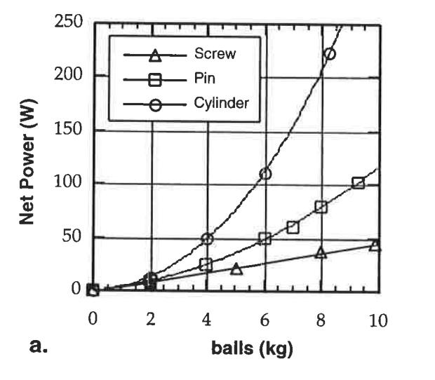
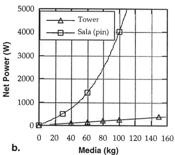
As the mill vessel is a cylinder, the amount of media is directly proportional to media height. Mill power draw was observed at different media levels in the laboratory and pilot scale units and, as can be seen from Figures 3a and b, different power responses were observed. The tower mill net power draw was directly proportional to the media level, while pin type stirrer and cylinder stirrer mill power had exponential relationships. This behavior suggest that there are differences in the power transfer from the different type of stirrers to the media. It seems that in the pin and cylinder type stirrer mills the friction forces are increasing with the media height due to increased normal force at the media contacts. The screw design of the tower mill has a "lifting" action and most of the media is placed inside the screw. This is why power draw has a linear response to the media height.
Media Density
Different types of media can be used in the stirred mills. The factor which most affects power draw is media density. In this study, the media density effect has not been investigated and it is assumed to be, based on the results from the literature (1, 3, 5, 9, 10), directly proportional to media density.
Media Size
It was observed that grinding media size affects stirred mill power draw significantly (1, 3, 8, 10). Figure 4 a presents the results obtained with the pilot tower and Sala (pin type) mill in terms of the net power draw/media weight. It can be seen that in both cases, power density increases with media size ie. coarser media draws more power. According to media velocity measurements in the transparent tower mill (1), media velocity also increases with the media size. It can be explained in fact that the number of media in a unit of volume is inversely proportional to the diameter cubed. Reduced number of contact points and increased force at the media contact results in higher media velocity and therefore the power draw.
There is no information published on effect of media size distribution on power draw. It can be expected that a "equilibrium charge distribution" or a mixture of different ball sizes would result in a higher power draw than a monosized charge due to increased charge density (lower porosity).
EMPIRICAL MODELLING
The most common way of modelling is to apply regression analysis techniques to experimental data, which, as a final result, would generate an equation describing the relationship between a specific system output and input variables. The resulting equation represents "the best fit" to experimental data and does not necessary describe the system correctly. Therefore, it can be safely used for predictions only in the range of the tested data. Such an empirical procedure could however, provide useful information about the system variables and their response.
Nonlinear regression techniques were applied to the screw, pin and cylinder stirred mills experimental data in order to fit three different types of equation. The following, purely empirical equation, was fitted first:
$$ P = a * \rho_{eff} * D^b * V^c * H^d * B^e $$ (1)
were: P = mill net power draw (W)
D = mill diameter (m)
V = stirrer tip speed (m/s)
H = media height (m)
B = ball size (mm)
\( \rho_{eff} \) = charge effective density (t/m3)
a,b,c,d,e = model constants
| Stirrer type | a | b | c | d | e | Data no: |
Av.
Err. % |
SD Err. | R |
|---|---|---|---|---|---|---|---|---|---|
| screw, \( l+p+i \) | 2.05 | 1.96 | 0.65 | 0.98 | 0.17 | 58 | 19.34 | 14.35 | 0.932 |
| pin, \( l+p \) | 4.13 | 1.15 | 0.72 | 2.00 | 0.27 | 73 | 14.72 | 17.80 | 0.991 |
| cylinder, i | 0.66 | / | 0.60 | 2.12 | 0.08 | 80 | 11.55 | 13.18 | 0.996 |
Note: I- laboratory; p - pilot; I - industrial mill data
Av. Err % - average model error, %; SD Err. % - error standard deviation, %; R - regression coefficient
The results obtained for each stirrer type are presented in Table 2 and plots of observed versus power obtained applying equation (1) for a particular stirrer type are presented in Figure 5. As can be seen, this type of model was able to fit the experimental data trend well. Error analysis however suggest that the model predictions may significantly differ from the experimental data.
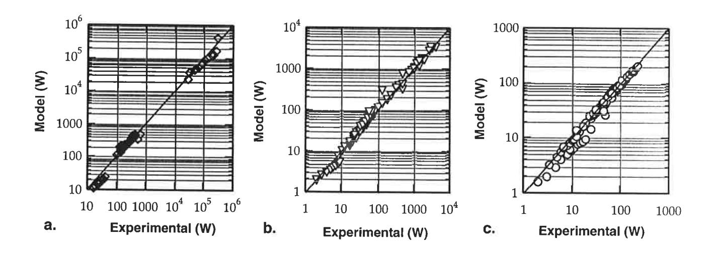
According to the obtained model constants, power draw depends on media height at power \( \sim 2 \) for pin and cylinder type stirrer and at power 1 for the screw type stirrer. This is a direct confirmation of Figure 3. The effect of stirrer speed was found to be similar (c = 0.6 - 0.72) which is in agreement with conclusions
from Figure 2. Media size effect was also found to be significant as it was suggested in Figure 4 a. Mill diameter was found to affect screw type mill at power ~ 2, while pin type mill at power 1.15. This is due to fact that only two mill diameters were tested.
The second form of the equation used was one proposed by Tüzün, (9) who states that power draw of a stirred mill is used to overcome the friction at the wall and bottom of the mill:
$$ P = 0.105 * N * B^{c} * (\rho_{eff} H * D^{2} * (k' * (D/3 + H) + k'' * V^{2})) $$ (2)
were: P = mill net power draw (W)
D = mill diameter (m)
V = stirrer tip speed (m/s)
H = media height (m)
B = ball size (mm)
\( \rho_{eff} \) = charge effective density (t/m3)
c, k', k''= model constants
In respect to model quality, similar results to equation (1) were obtained fitting the equation (2). It suggest that this model is basically empirical one, and that exponents for mill diameter and media height were correctly predetermined.
MECHANISTIC MODEL
A mechanistic model describes a process using the laws of physics. It can be more or less detailed depending on the complexity of the process, and more important, how detailed the study of the process has been and how well it was understood. The stirred mill mechanistic model in this work is obtained based on the analysis of forces acting on the media and media motion studies.
Friction is considered to be the major energy consumer in a stirred mill, where friction forces are dependent primarily on distribution of gravitational and centrifugal forces. Media motion was studied using a transparent laboratory size mill, photography and high speed video techniques for measuring the media 'elocities.
Tower Mill Model
Media Motion Modelling
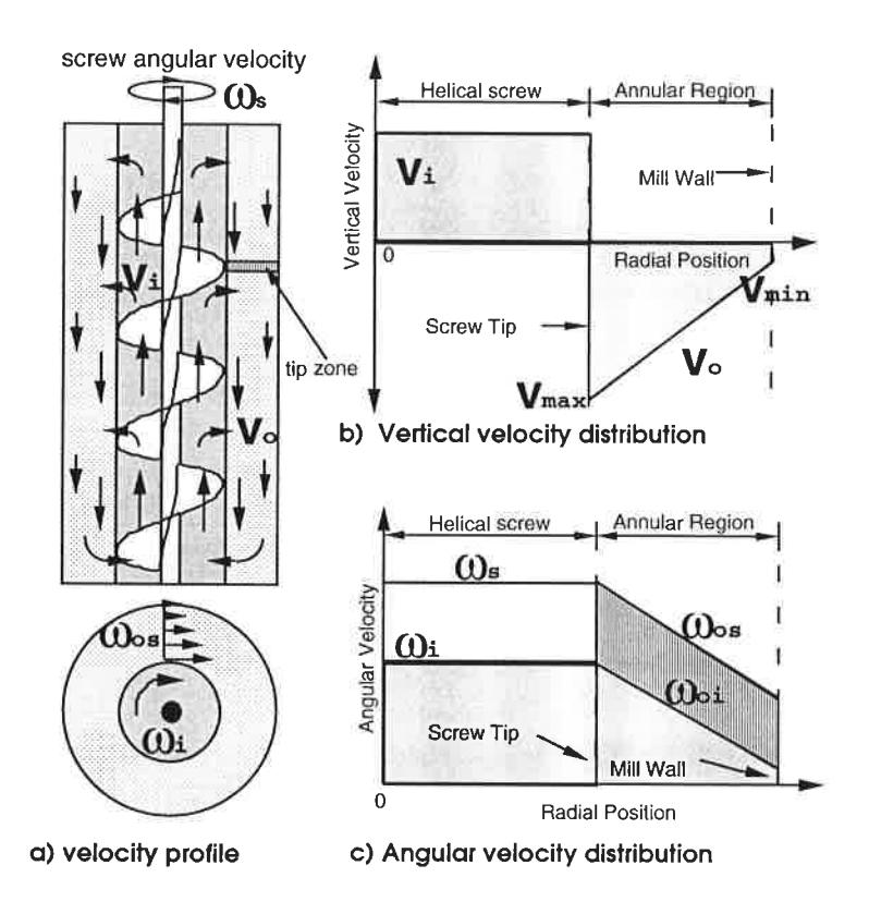
The media motion occurring within the tower mill is a direct result of the lifting and rotating action generated by the helical screw. From the observations made from high speed videoing (1), the balls within the central screw column (shaft to stirrer tip) are carried upward on the screw flights at a specific radial position. This rotating charge ascends the screw column at the same angle as screw flights. When the grinding media nears the top of the charge, they disperse towards the outer mill wall. From here, the grinding media spiral downward within the annular region (stirrer tip to mill wall), again holding their radial position. A graphical representation of the angular and vertical velocity profile observed in the transparent mill is depicted in Figure 6.
Based on experimental results, the following equations were obtained to model media velocities inside the tower mill:
• screw region:
$$ v_i = v_s^* (n + m^*B) $$ (4)
'where: \( \omega_s \) , \( \omega_i \) = screw and media angular velocity inside the screw, respectively (1/s)
\( v_s \) , \( v_i \) = screw and media vertical velocity inside the screw, respectively (1/s)
B = media size (mm)
n, m = constants
◆ outer region
- screw tip zone $$ \omega_{os} = \omega_{s} - p/B^{*} rt $$ (5)
- "out of tip" zone $$ \omega_{oi} = (\omega_s - p/B * rt) * (n + m * B) $$ (6)
where: \( \omega_{os} \) = annular angular velocity in the tip zone (1/s)
\( \omega_{oi} \) = annular angular velocity in the "out of tip" zone (1/s)
\( \omega_s \) = screw angular velocity (1/s)
rt = radial distance from the screw tip (m)
n, m = constants
The following expression for the media falling velocity profile was derived based on Figure 6 b:
$$ v_o = 2 * v_s * (n + m*B) * \frac{Ds}{D - Ds} * (1 - \frac{rt}{D - Ds}) $$ (7)
where: D, Ds = mill and screw diameter respectively (m)
Power Model
The following forces are assumed to exist inside a vertical stirred mill:
Gravitational (media weight); Centrifugal; Friction
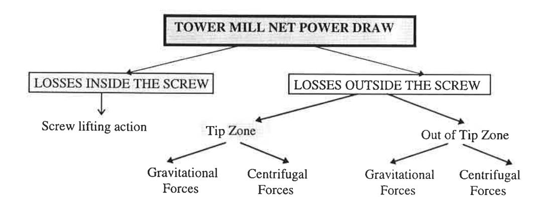
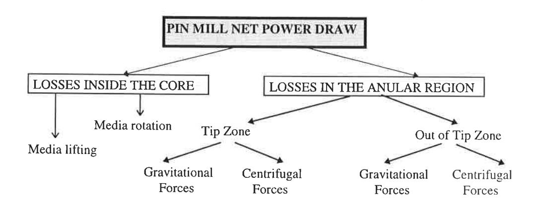
Mill power draw is the sum of the power losses in the previously explained areas in the mill. The structure of the power losses is presented in Figure 7.
The power needed to set in motion the media inside the screw can be calculated using the analogy with power screws:
$$ P_{i} = T_{i} * \omega_{s} = F_{b} * \frac{d_{m}}{2} * \frac{\operatorname{tg} \alpha + \mu}{1 - \mu * \operatorname{tg} \alpha} * \omega_{s} $$ (8)
were: \( P_i \) = power needed to move the media inside the screw (W)
\( T_i \) = lifting torque (Nm)
\( \omega_s \) = screw angular velocity (1/s)
\( F_b \) = gravitational force (media weight) (N)
\( d_m \) = screw mean diameter (m)
\( \alpha \) = helix angle of the screw (°)
\( \mu \) = coefficient of friction
Power needed to rotate the charge outside the screw can be calculated based on the friction between the balls. Friction between two balls is determined by the pressure from the load over the balls and centrifugal force. Friction force multiplied by the ball velocity will give the power:
$$ P_o = \sum (F_g + F_c) * \mu * v_r $$ (9)
were: \( P_0 \) = power needed to rotate the charge outside the screw (W)
\( F_g \) = gravitational force at the ball contact (N) \( F_c \) = centrifugal force at the ball contact (N) \( v_r \) = relative velocity between two balls (m/s)
Vertical Pin Mill Model
The stirring action of the pin type stirrer is different than the screw type one. The best description of the media motion with the pin type stirrer was given by J. Zheng et al, (10):
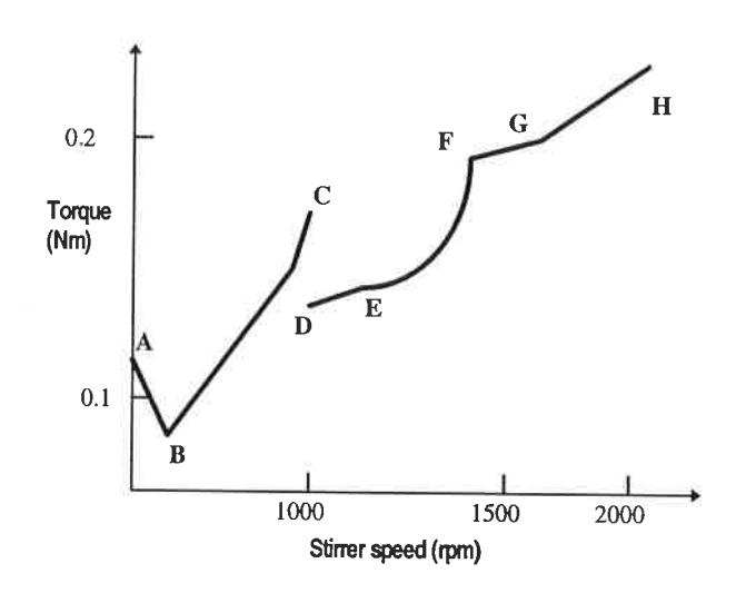
"Before rotation occurs, the torque increases and then drops sharply as rotation commences (region AB). This is a transition from static to dynamic friction, and torque at the point B is analogous to yield stress in non-Newtonian fluids. Thereafter the torque increases with rotational speed (region BC). Observation showed that the spindle arms (pins) channel trough largely stationary media, forming cavities at the trailing edge. At lower speeds, the cavity fills with media and at higher speeds, filling is not fast enough, so that a continuous channel is formed. Towards the upper end of the region BC the entire media mass begins to rotate and the upper layers begin to levitate into liquid resulting in a drop in solid concentration and sharp drop in the medium effective viscosity. This drop in concentration and consequently, in viscosity accounts for the drop in torque (CD). At still higher speeds, the media becomes further dispersed (region DEF). Later, the media becomes fully dispersed, attaining uniform concentration (region EF). Finally, the system develops a marked vortex and media tends to centrifuge towards the walls of the tank (region FGH)".
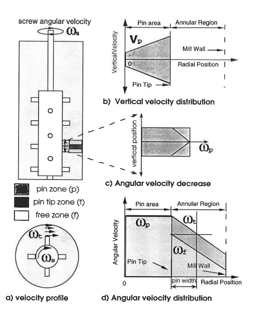
Using the same observation technique as for the tower mill, it was found that media motion with the pin type stirrer has a pattern similar to that observed by J. Zheng et al, (10) in the BC region. The highest nedia angular velocities were observed at the pin tips, slowing down towards the mill wall. In between the pins a velocity gradient was found. A significant media displacement in vertical direction was also found. According to these observations, the following zones were separated (see Figure 9 a):
◆ core zone, between the shaft body and pin tip, where pin channel trough media causing the rotation and pulsation of the media in a vertical direction. Media speed in vertical direction vp is equal to (see Figure 9 b):
Angular velocity drop in vertical direction \( \omega_p \) (Figure 9 c), can be expressed as follows:
where: r = radial distance from the mill center (m)
a = vertical distance from the pin (m)
\( \omega_s \) = stirrer angular velocity (1/s)
z = constant for a particular media type
- pin tip zone, between the pin tip and mill wall, where media is rotating due to the pin tip action. The angular velocity, \( \omega_t \) model (Figure 9 d) is of the same form as for the tower mill ( \( \omega_{os} \) ).
- free zone, where the rotational is transferred by the media from pin tip and media from the core zone. The angular velocity, \( \omega_f \) model (Figure 9 d) is of the same form as for the tower mill ( \( \omega_{oi} \) ).
Power Model
Irrespective of the differences in the stirrer design, the pin mill power model structure is the same as the tower mill one (Figure 10). Based on media motion information obtained, it was concluded that power losses can be described in the same way as for the tower mill. In particular, power loss calculations in the region between the pin tips and mill wall, including the loss at the mill bottom and wall, are the same as for the tower mill.
Power needed for the vertical displacement inside the core is equal to the product of the gravitational force acting on the pin and displacement speed, along the pin:
$$ P_{v} = \sum_{1}^{n} F_{g} * \mu * v_{p} $$ (12)
were: \( P_v \) = power for vertical displacement (W) \( F_g \) = gravitational force acting on the pin (N) n = number of pins \( v_p \) = media vertical velocity (m/s) \( \mu \) = coefficient of friction between the balls
In contrast to tower mill inner screw area, there is a angular speed gradient in the vertical direction inside the core region (Figure 9 c). Therefore, friction losses exist in this direction due to relative motion between the media. Power loss due to the media friction inside the core zone \( P_{prv} \) , can be calculated as follows:
$$ P_{prv} = (I/B) * \sum_{0}^{s/2} \mu * F_g * v_{tr} $$ (13)
were: Pprv = power losses due to the media rotational velocity difference in vertical direction,
for one pin (W)
\( F_g \) = gravitational force at the ball contact (N)
\( v_{tr} \) = media tangential velocity inside the core (m/s)
\( \mu \) = coefficient of friction between the balls
l = pin length (m)
s = vertical distance between two nearest pins (m)
B = ball diameter (m)
CONCLUSION
This work has shown that an empirical approach to modelling the stirred mills power is not satisfactory. The proposed empirical models fits reasonably the trend of the experimental data, but model residuals suggested that model accuracy is not satisfactory. More sophisticated regression techniques may be able to produce better fitting results but, generally, application of the empirical models will be limited by the extent of the data base used for its development.
A new stirred mill power model was presented which is a generic mechanistic model as it includes a detailed description of the media motion (velocity profiles) and distribution of forces inside the mill. The general model structure is the same for different stirrer designs and is based on friction losses at individual contact points. Stirrer design and geometry is directly incorporated into the model which provides an excellent basis for the mill power scale up. The main achievement of the model is its ability to provide the information on media collision rate and energy. It can therefore be directly incorporated into a generic breakage model.
ACKNOWLEDGEMENTS
The authors would like to thank sponsors of the AMIRA 336A Fine Grinding project who sponsored this research.
REFERENCES
- 1. Duffy, S. M., "Investigation into the Performance Characteristics of Tower Mills", Masters thesis. University of Queensland, JKMRC, 1994.
- Guillaneau, J-C, Olofsson, O, Durance M-V, Villeneuve, V.,. "Modelling of the Sala Agitated Mill (SAM) Using BRGM Pilot Plant Data" <u>APCOM XXV Conference</u>, AusIMM, Brisbane, Australia. 1995, 325-332.
- 3. Herbst, J.A., and Sepulveda, J.L.,. "Fundamentals of Fine and Ultrafine Grinding in a Stirred Ball Mill" <u>International Powder and Bulk Solids Handling and Processing</u>, Proceedings held Rosemount Illinois, 1978, May 16-18, 452-470
- 4. Jenczewski, T.J., "The grinding of Organic Dyestuffs", <u>Cand. J. Chem. Eng.</u>, Vol. 50, 1972, Feb., 59-65.
- Novosad, J., "Studies on Granular Materials IV" <u>Collection of Czechoslovak Chemical Communications</u>, Vol.29, 1965. 3247-3262
- 6. Sadler III. L.Y., Stanley. D.A. and Brooks. D.R., "Attrition mill Operating Characteristics" Powder Technology, 12, 1975. 19-28.
- 7. Sepulveda, J., "A detailed Study on Stirred Ball Mill Grinding" University of Utah PhD Thesis 1981.
- 8. Tüzün, M.A., Loveday, B.K., "Fine milling of Chromite Sand in a 5-litre Stirred Ball Mill" Minerals Eng., vol 7, 1994. 551-560.
- 9. Tüzün, M.A., "A detailed Study on Comminution in a Vertical Stirred Ball Mill" PhD Thesis. University of Natal. South Africa, 1993.
- 10. Zheng, J., Harris, C.C., and Somasundaran, P., "Power consumption of the Stirred Media Mills" Minerals and Metallurgical Processing., February., 1995. 34-40.
- Weith, H. and Schwedes J., "Scale-Up of Power Consumption in Agitated Ball Mills" Chemical Engeneering Technology vol. 10, 1987. 398-404.